


For DRIVERS, MECHANICS & FOREMEN.
Page 21
If you've noticed an error in this article please click here to report it so we can fix it.
A PRIZE OF TEN SHILLINGS is awarded each week all other.? are paid for at the rate of a penny a lane, with an published. Mention VOW employer's name, in confidence, Commercial Motor," 7-15, Ros
to the tender of the best letter which we publish on this page ; allowance for photographs. All notes are edited before being as evidence of good faith, Address, D. M. and F., " The ebery Avenue, London, E.C. .1.
Lamps Alight— On Saturday, the 8th June, light your lamps at 9.41 in London, 10.52 in Edinburgh, 10.9 in Newcastle, 10.4 in .Liverpool, 9.54 in Birmingham, 9.51 in Bristol, and 10.46 in Dublin.
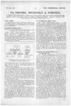
Crankshaft Grinding Brace.
The sender of the following communication has been awarded the los. prize this week.
[1864] " H.M." (West Bromwich) writes :—" The sketch enclosed herewith [which we have had redrawn.—En.] shows a crankshaft grinding brace which I recently saw applied in the manufacture of automobile crankshafts, which appeared to me to he an efficient brace which will do a, great deal to eliminate the danger of springing during turningand grinding of the crankpins.
" It consists of two V blocks made of aluminium, fastened by clamp screws over the centre line of the shaft, sufficient clearance being allowed between the blocks for any variation which may occur in the diameter of the crankpin.
" It will be noticed that the lower end of the V block is provided with a hinged strap-clamp and is secured by a stud, whieh allows the light, hollow tube, acting as a brace rod, to be removed from or clamped quickly into place. This tube has a knurled head screw at one end for adjusting it between the throw webs of the shaft and a knurled eheek nut at the other end to keep it from working loose after adjustment. Two knurled set pins are provided upon the opposite end of the V block, and act as a brace on that side of the shaft.
"After adjusting this brace to the shaft as shown, the lower pins are ground to size. The brace rod is then removed and the upper pins are finished in the same manner. The complete attachment may then be removed, and the line bearings finished in the usual way in a separate operation. "Care must be taken in adjusting the screwed pins so as to counter-balance the pressure of the grinder centres, so that the shaft will not be subjected to spring or be out of parallel with the bearings for if this is neglected it is likely to -cause the pistein to slap and knock against the walls of the cylinder at each end of its travel. The use of this brace eliminates this trouble, and, provided it is designed to be in perfect balance on the shaft, it will also assist in preventing chatter marks and in producing true bearings quickly,"
For Troublesome Boiler Tubes.
{1865j " KB." (Whittlesf old) writes :—",A large number of steam wagons of all descriptions and types are operating on important national work, and, generally:they are to be found at work some distance from their bases. I have found, in conversation with many drivers, that a enerticulat experience Of my own in connectionewith steam wagons is by no means uncommon, and I have, therefore, no hesitation in putting it before you as being worthy of inclusion amongst the useful hints and tips which form a regular feature Of your paper, appearing on the 'Drivers, Mechanics and Formen's page. Almost invariably do these steam wagons develop leaky tubes. It is undoubtedly due to the. fact that the drivers are compelled to take in so many different kinds of water. Merely expanding the tubes does not seem to be, in any sense of the word, a permanent remedy. My present method has proved most, successful. "1 commence operations by pushing the tube a little further—a sixteenth of an inch or so—along the boiler, away from the firebox. and afterwards expanding them at both ends. By this Illeallb it seems as though a sufficient bed is obtained for the expanded portion of the tube and better results arc experienced."
Replacing the Timing Wheels of a Foreign-built Car.
[1866] " E.O.W." (Smethwick) writes : ---" We have in use an old Delauna,y-Belleville car which is doing yeoman service as a one-ton van. A short time ago, one of the timing wheels, which were built up of alternate layers of fibre and brass, stripped a few teeth. No spares were obtainable From either the English agents or from the French makers. It was, therefore, necessary to have a new one made. I used the existing wheel as a pattern, filling in the spaces between the teeth with beeswax, and putting on ale in. all round to allow for contraction. This was quite successful so far as it went, and I secured a suitable casting, turning it up as a blank. The difficulty arose when ,we endeavoured to get the teeth machined.
"IL was found, on examination by a firm of gear cutters, that these teeth were made to French standards. The firm had no cutters suitable, and, of course, for the sake of one or two wheels it was not worth while to make these cutters. Cutting them to the standard English shape meant that the teeth would be too thick from the pitchline outwards. It was, therefore, decided •to cut them to the standard form and then trim them up afterwards, and,of course, upon me fell the responsibility of trimming the teeth. I had two alternatives, either to file them up by hand, or to rig up some tackle on the lathe for doing the work. Clearly the latter was likely to result in the most mechanical job, and after a little consideration I arrived at the following method :-
" I made a sort of reamer or drill, the end of which was the same shape in cross section as I wished the space between the teeth to be. This was carried by the lathe chuck. The wheel I mounted on a suitable mandrel, secured this mandrel to an angle plate, and bolted the angle plate to the cross slide of the lathe. On the angle plate also I -mounted a pawl, the end of which fitted into one of the teeth spaces. With this tool, and using this jig, I trimmed up each space to the correct form, and by releasing the pawl, tooth by tooth, was able also to ensure that the teeth were accurately set out."