


Patents Completed.
Page 22
If you've noticed an error in this article please click here to report it so we can fix it.
TAXIMETER. — Werner, — No. 1,530, dated 18th January, 1907.—The road wheel
carries a stud (k) and on a squared spindle 0) is an arm (j). This arm lies in the path of the stud (k), so that, at every revolution of the wheel, the arm is deflected and carries with it the spindle. On the spindle is a double cam (h, hi) which bears against the face of a spring-controlled stirrup (a). The stirrup is connected, by a Bowden wire, with any convenient device for operating the taximeter, so that at each oscillation of the stirrup the taximeter is operated, LIARICATOR.—Alley and Another.— No. 21,893, dated 4th October, 1906.—In order that the usual form of lubricator used for light lubricant may be readily filled with heavy lubricant, the lubricator {A) has a screw-threaded nozzle (E) adapted to receive a pump (F). In the lubricating nozzle is a non-return valve {B), and the pump contains a valve (L). When the pump is secured in position, the lower end of the valve (L) rests upon the nozzle (E), and is thus lifted from its seating, whereupon the plunger (H) can be depressed, and the lubricant thereby forced past the valve (B) into the lubricator. When the pump is removed, the valve (L) closes automatically and prevents waste of lubricant. It will thus be seen that the lubricant can be introduced to the lubricator without risk of foreign Flatter becoming mixed with it. LUBRICATOR.—Brown and Another. —No. 20,006, dated 8th September, 1906. —This lubricator is adapted to feed measured quantities of lubricant to the parts to be lubricated. A conduit (d) communicates with a pump which forces lubricant through the conduit into the chamber (a). The chamber (a) is separated from a second chamber (b) by a spring-controlled lift -valve (g) and, at each reciprocation of the pump, this valve is lifted against its spring so that the lubricant can pass into the chamber (b). This chamber, when the apparatus is working, is already full of lubricant, but, communicating with it, is a barrel (k) wherein a spring-controlled plunger (I) is mounted. it follows, therefore, that the oil forced into the chamber carries the plunger (1) back against the controlling spring, with which it is provided, and, after the charge has entered the chamber (b), the valve (g) closes against any return from the chamber (b) to the chamber (a), but opens communication with a chamber .7`). The plunger (1) now advances, under the action of its spring, and forces the lubricant from the chamber (8) into the chamber (f), whence it travels to the parts to be lubricated by a conduit (e). A stop (m) regulates the limit of movement allowed the plunger (1) and thus controls the amount of lubricant passed to the conduit (e) at each operation.
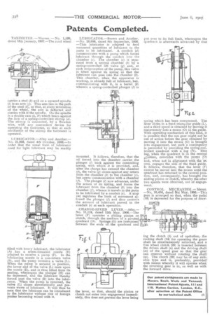
CHANGE-SPEED LEVER.—Atha.No. 11,124, dated 12th May, 1906.—The lever (F) operates a sliding pinion or clutch, through the medium of a pivoted quadrant (D). Springs (G) are interposed between the ends of the quadrant and
the lever, so that, should the pinion or clutch not enter into engagement immediately, this does not prevent the lever being put over to its full limit, whereupon the quadrant is afterwards advanced by that spring which has been compressed. The lever slides in a fixed triangular guide (L), and a third speed is obtained by moving it transversely into a recess (0) in the guide. With operating mechanism of this kind, it is possible that the one gear might not be out of action before the gear obtained by moving it into the recess (0) is brought into engagement, but such a contingency is prevented by providing the spring-con. trolled quadrant with • a lug (N). This lug, when the quadrant is in the central
coineic1. with the recess (0) and, when not in alignment with flit recess, engages the side of the fixed guide. It follows, therefore, that the lever (F) cannot be moved into the recess until the quadrant has returned to the central position, and, consequently, has brought the sliding pinion or clutch, whereby the other two speeds were obtained, out of engagement.
CONTROL MECIIANISM.—M6yer, —No, 10,416, dated Srd May, l006.—This gear is arranged so that, when the pedal (1g) iS depressed for the purpose of dt4W • ing the clutch (b) out of opetafesof the rocking shaft (14) for operating the gears shall be simultaneously unlocked, and a free wheel clutch (20) is inserted betWeen the driven shaft (a) and the driving shaft • (m) of the speed gear so that the gear can overrun without rotating the shaft: (m). The clutch (20) may be of any snit.able type and is, preferably, provided' with means whereby it will operate when the reversing gear is in, as well as with the forward drive.