 1
1 2
2 3
3 4
4 5
5 6
6 7
7 8
8 9
9 10
10 11
11 12
12 13
13 14
14 15
15 16
16 17
17 18
18 19
19 20
20 21
21 22
22 23
23 24
24 25
25 26
26 27
27 28
28 29
29 30
30 31
31 32
32 33
33 34
34 35
35 36
36 37
37 38
38 39
39 40
40 41
41 42
42 43
43 44
44 45
45 46
46 47
47 48
48 49
49 50
50 51
51 52
52 53
53 54
54 55
55 56
56 57
57 58
58 59
59 60
60 61
61 62
62 63
63 64
64 65
65 66
66 67
67 68
68 69
69 70
70 71
71 72
72 73
73 74
74 75
75 76
76 77
77 78
78 79
79 80
80 81
81 82
82 83
83 84
84 85
85 86
86 87
87 88
88 89
89 90
90 91
91 92
92 93
93 94
94 95
95 96
96 97
97 98
98 99
99 100
100 101
101 102
102 103
103 104
104 105
105 106
106 107
107 108
108 109
109 110
110 111
111 112
112 113
113 114
114 115
115 116
116 117
117 118
118 119
119 120
120 121
121 122
122 123
123 124
124 125
125 126
126 127
127 128
128 129
129 130
130 131
131 132
132 133
133 134
134 135
135 136
136 137
137 138
138 139
139 140
140 141
141 142
142 143
143 144
144 145
145 146
146 147
147 148
148 149
149 150
150 151
151 152
152 153
153 154
154 155
155 156
156 Elementary electrics for mechanics
Page 92
If you've noticed an error in this article please click here to report it so we can fix it.
Round the horn
THE VEHICLE MECHANIC can, as I said before, do quite a lot towards ridding a radio-equipped vehicle of local interference. Here I must make it clear that it is not my intention to turn mechanics into electricians or cross swords with the trade unions but to allow for the fact that small hauliers cannot afford a fulltime electrician. Therefore it may be necessary to call in outside assistance for small electrical faults or put the vehicle in the usual queue at the agent if the failure is found late in the day.
But there is no reason at all why, with the aid of a little information, the mechanic should not be able to deal with these minor, but often delay-making electrical faults.
For example, ability to give audible warning of approach is a legal requirement, like side lamps and screen wipers, so what is a mechanic to do if a driver refuses to take a vehicle out without the horn working, and there is none in stock?
Twin horns are preferred these days and when a malfunction occurs it is more often than not in the circuit rather than the horn itself.
One extra item in the twin horn circuit can be a relay. The single earth-return horn is a simple enough set-up, with a lead running from the power supply direct to the horn input terminal. Of course, the horn will not operate until the circuit is complete to earth via the horn button. Therefore as the battery is earthed on one side, closing the horn switch should blow the horn.
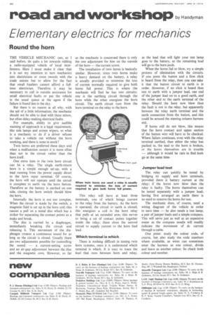
Internally the horn is not too complex. When the circuit is made by the switch, a magnetic field is set up in the horn coil; this causes a pull on a metal disc which has a striker for separating the contact points as a make and break.
The disc is carried by a diaphragm, immediately breaking the circuit and releasing it. This movement of the diaphragm creates a continuous sound for as long as the circuit is closed. Usually there are two adjustments possible for controlling the sound — a current-setting screw and an air-gap adjustment between the disc and the magnetic core. However, so far as the mechanic is concerned there is only the one adjustment for him on the outside of the horn — the current screw.
The installation of twin horns is basically similar. However, since twin horns make a heavy demand on the battery, a relay is usually provided to minimize the loss of current normally required to give both horns full power. This is where the mechanic will find he has two circuits: one is the earthing circuit through the horn while the other energizes the horn circuit. The earth circuit runs from the horn terminal on the relay to the horn.
This relay will have at least three terminals, one of which brings current to the relay from the battery. As the horn is operated, the circuit to earth is closed; this energizes a coil in the horn relay that pulls at an extended arm; this serves to bring a set of contact points together inside the relay; these close the second circuit to supply current to the horn feed lead.
Which temiinal is which There is nothing difficult in testing twin horn systems, once it is understood which terminal is which. It is easy to trace the lead that runs between horn and relay, as the lead that will light your test lamp goes to the battery, so the remaining lead will go to the horn push.
When the horns fail to blow, try a simple process of elimination with the circuits. If you press the button and a firm click is heard from the relay, then you can take it that the button circuit to earth is in order. However, if no click is heard then test to earth with a jumper lead, one end of the jumper lead on to a good earth, and the other end to the earth terminal of the relay. Should the horn now blow then the fault is not in the relay, but apparently between the relay earth terminal and the earth connection from the button, and this could be around the steering column harness exit.
If horns still do not blow, this means that the horn contact and upper section of the button wire will have to be checked. Where failure continues, even with the relay terminal earthed, then either the relay has packed in, the lead to the horn is broken, or the horns themselves are in trouble — although it would be rare to find both go at the same time.
Jumper lead test The relay can quickly be tested by bridging its supply and horn terminals, provided there is battery current at the relay; if the horns now blow then the relay• is faulty. The horns themselves can be tested separately with a jumper lead; having first arranged an earth there is no need to remove the horns for test.
The mechanic does, of course, need a wiring diagram of the vehicle in order to save time — he also needs a test lamp, a pair of jumper leads and a simple compass. This will serve just as well as an expensive meter as the compass needle will readily indicate the movement of dc current through a cable.
One point: study the colour code, of course, but also study the code numbers where available, as wires can sometimes enter the harness as one coloui, divide and leave as another colour. So check both colour and number.