


A Sensitive Air hydraulic Braking System
Page 42
If you've noticed an error in this article please click here to report it so we can fix it.
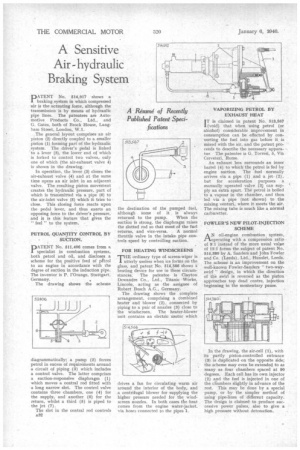
DATENT No. 514,917 shows a
braking system in which compressed air is the actuating force, although the transmission is by means of hydraulic pipe lines. The patentees are Automotive Products Co., Ltd., and G. Gates, both of Brock House, Longhorn Street, London, W.1.
The general layout comprises an air piston (2) directly coupled to a smaller piston (I) forming part of the hydraulic system. The driver's pedal is linked to a lever (3), the lower end of. which is forked to control two valves,, only one of which (the air-exhaust valve 4) is shown in the drawing.
In operation, the lever (3) closes the air-exhaust valve (4) and at the same time opens an air inlet in an adjacent valve. The resulting piston movement creates the hydraulic pressure, part of which is transmitted via a pipe (6) to the air-inlet valve (5) which it tries to close. This closing force reacts upon the pedal lever, and thus exerts an opposing force to the driver's pressure, and it is this feature that gives the " feel " to the system. • PETROL QUANTITY CONTROL BY SUCTION.
PATENT No. 511,406 comes from a specialist in combustion systems, both petrol and oil, and discloses a scheme for the positive feed of pgtrol to an engine in accordance with the degree of suction in the induction pipe. The inventor is P. I'Orange, Stuttgart, Germany.
The drawing shows the scheme
diagrammatically; a pump (2) forces petrol in excess of requirements around a circuit of piping (3) which includes a control valve. The latter comprises a suction-responsive diaphragm (1) which moves a central rod fitted with a long narrow slot. The control valve contains three chambers, one (4) for the supply, and another (6) for the return, whilst a third (5) is piped to the jet (7).
The slot in the central rod controls o32 the destination of the pumped fuel, although some of it is always returned to the pump. When the suction is strong, the diaphragm raises the slatted rod so that most of the fuel returns, and vice-versa. A normal throttle valve in the intake pipe controls speed by controlling suction.
FOR HEATING WINDSCREENS
THE ordinary type of screen-wiper is utterly useless when ice forms on the glass, and patent No. 514,566 shows a heating device for use in these circumstances. The patentee is Clayton Dewandre Co., Ltd., Titanic Works, Lincoln, acting as the assignee of Robert Bosch A.G., Germany.
The drawing shows the complete arrangement, comprising a. combined heater and blower (2), connected by piping to a pair of nozzles (3) close to the windscreen. The heater-blower unit contains an electric motor which drives a fan for circulating warm air around the interior of the body, and a centrifugal blower for supplying the higher pressure needed for the windscreen nozzles. In both cases the heat comes from the engine water-jacket, via hoses connected to the pipes 1.
I T is claimed in patent No. 513,567
(void) that when using petrol (or alcohol) considerable improvement in consumption can be effected by converting the fuel into gas before it is mixed with the air, and the patent proceeds to describe the necessary apparatus The patentee is G. Torresi, 5, Via Cerveteri, Rome.
An exhaust box surrounds an inner barrel (4) to which the petrol is fed by engine suction. The fuel normally arrives via a pipe (1) and a jet. (2), but for acceleration purposes a manually operated valve (3) can supply an extra spurt. The petrol is boiled to a vapour in the chamber, and then, led via a pipe (not shown) to the mixing venturi, where it meets the air. The mixing tube is much like a normal carburetter.
FOWLER'S NEW PILOT-INJECTION SCHEME
AN oil-engine combustion system, fl.operating with a compression ratio of 9:1 instead of the more usual value of 15:1 forms the subject of patent No, 514,380 by A. Sanders and John Fowler and Co. (Leeds), Ltd., Hunslet, Leeds, The scheme is an improvement on the well-known Fowler-Sanders " two-wayswirl " design, in which the direction of the swirl is reversed as the piston approaches top dead centre, injection beginning in the momentary pause.
In the drawing, the air-cell (1), with its partly piston-controlled entrance (3) is duplicated on the opposite side; the scheme may even be extended to as many as four chambers spaced at 90 degrees. Each cell has its own injector (2) and the fuel is injected in one of the chambers slightly in advance of the rest. This may be done by a special pump, or by the simpler method of using pipe-lines of different capacity. The design is claimed to produce successive power pulses, also to give a high pressure without detonation.