


PATENTS SUMMARIZED.
Page 22
If you've noticed an error in this article please click here to report it so we can fix it.
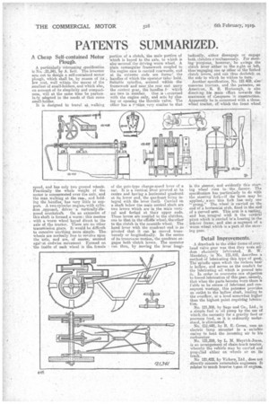
A Cheap Self-contained Motor Plough.
A partieularly interesting specification is No. _21,341, by A. bell. The inventor sets out to design a self-contained motor plough, which shall be, by reason of its low cost, well within the means of the smallest of small-holders, and which also, on account of its simplicity and compactness, will at the same time be particula.ly adapted to the needs of that same small-holder.
It is designed to travel at walking
speed, and has only two ground wheels. Practically the whole weight of the motor is concentrated over the axle, and the man walking at the real, and holding the,handles, has very little to sup. port. A two-cylinder engine/ with cylinders _opposed, drives. 'a vertically-disposed crankshaft. On an extension of this shaft is formed a worm: this meshes with a worm wheel keyed direct to the axle of the tractor. There are no other transmission gears. It would be difficult to conceive anything more simple. The. wheels are normally free to revolve upon the axle, and are, of course, secured agai-st endwise movement Formed on the inside of each wheel is the_ female portion of a clutch' the male portion of which is keyed to the axle, to which is also secured the•driving worm wheel. A plain rectangular framework coupled to the engine case is carried rearwards, and at its extreme ends are forme-' the handles of which the operator takehold. Suitable spindles, secured within the framework and near the rear. eint carry
the control gear, the handles which are two in number. One :a ..oncerned with the engine only, and acts by closing or opening the throttle valve. The other has a ration very similar to that
of the gate-type change-speed lever of a car. It is a vertical lever pivoted at its centre and having a horizontal quadrant at its lower end, the quadrant being integral with the lever Itself. Carried on a shaft below the main control shaft are two levers which are in the main verti. cal and forked at their upper ends. These levers are Coupled to the clutches, one to that in the offside wheel, the other to the clutch in the nearside wheel. The hand lever with the quadrant end is _so pivoted that it can lle •moved transversely or longitudinally. In the centre of its transaerse motion, the quadrant, engages both -clutch levers. The operator can then, by moving the lever longi tudinally, either disengage or engage both. clutches simultaneously. For steering • purposes, however, he swings the clutch lever either to the r.ght or left, thus engaging one or ether of the forked clutch levers, and cab thus declutch on the side to which he wishes to turn,
Another specification, No. 121A38, also concerns tractors, and the patentee, an American, R. B. Hartsough, is also directing his main effort towards the maximum of cheapness in construction. Apparently he is concerned with a threewheel tractor, of which the front wheel
is. the ateerer, and evidently this steering wheel runs in the furrow. The specification has particularly to do ivith the steering fork—if the term may be applied/ ince this fork has only one
prong." The wheel is carried on the end of a horizontal stub, fixed in the end of a curved arm. This arm is a casting, and has integral with it the vertical pivot which is carried Ma hearing in the tractor frame, and also a segment of a worm wheel which is a, part of the steering gear.
Detail Improvements.
A drawback to the older forme of over.• head valve gear was that they were seldom efaciently lnbricated. R. W. Maudslay, in Nn. 121,410, describes a method of lubricating this type of gear. The spindle upon which the rockers bear is hollow, and serves as the conduit for the lubricating oil which 141 poured into it. In order to overcome ore objection to forced lubrication of this gear, namely, that when the parts become worn there is Fable to be excess of lubricant and consequent wastage, this patentee provides an outlet to the hollow shaft, leading to the overflow, at a level somewhat higher than the highest point requiring lubrication.
No. 121,300, by Sage and Co., Ltd., is a simple fuel die oil pimp by the use of which the necessity for a gravity feed or pressure feed, as it is ordinarily understood, is eliminhted. • • No. -121,448,• by R, E. Green, .uses an electric lamp mounted in a suitable casing to heat the incoming air to his carburetter No. 121,359, by L. M. Meyriek-Jones, is an arrangement of chain-track tractor, whereby the vehicle may he cairied and propelled either on wheels or on its track.
No 121,422, by Vickers Ltd., does not directly concern automobile engineers. It relates to much heavier twes. of engines.