


Municipal Appliance Featuring Mechanical Ingenuity
Page 25
If you've noticed an error in this article please click here to report it so we can fix it.
In the Mechanism of the Scammell Road-sweepercollector are Embodied Many Points of Interest that Promote Its Efficiency of Operation
AMONG the products of British commercial-vehicle manufacturers, those from the works of Scammell Lorries, Ltd., can practically always be relied upon to provide plenty of subject matter for study by persons interested in ingenious mechanisms. No exception to this rule is the Scammell roadsweeper and collector, and this is no more than would be expected, for such machines afford plenty of scope for mechanical-engineer designers.
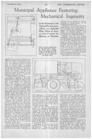
A general description of this municipal appliance appeared in The Commercial Motor on May 19, 1939, shortly after its introduction, but little was then stated about its mechanical details, the description having been confined to a comprehensive summary of its main features and capabilities. In the accompanying drawings, however, which have been based on those illustrating Patent specification No. 527,625, which deals fully with this sweeper collector, the methods of driving the various brushes, and rotors, and of controlling the former are clearly shown.. They are notably interesting.
Readers will remember that the machine is constructed as a semi-trailer for use in conjunction with a Scammell mechanical horse, that it is provided with its own power unit for operating the sweeping and collecting mechanism and that engine and gear are controlled by an operative seated in a suitable position of vantage on the trailing appliance. One of the most outstanding points is that this attendant is enabled to control the lateral position of the main brush, which is adjustable in this respect and so situated that it can sweep right up to the near-side boundary of the road.
By this means the onus of steering a course which ensures effective gutter sweeping is lifted from the shoulders of the driver of the outfit. Difficulty has been experienced in driving with the necessary skill to accomplish this operation, whereas it is quite easy for the attendant on the trailing unit to keep the brush touching the kerb, irrespective of variations in the distance of the machine from the side of the road as the outfit travels along.
There are two brushes (1 and 2). Brush 1 is obliquely positioned and sweeps from the extreme side towards, roughly, the centre of the machine, whilst brush 2 is precisely transverse and, as its main function, flings the sweepings into the mouth of the conveyor. This brush, it will be noticed7 is made in two parts, the smaller being set at a slight angle to the larger. The former is described, self-explanatorily, as a corrector brush.
Supporting the forward ends of the bearers (3) of brush 1 are two swing ing links (4). These can be moved laterally by a flexible connection (5) running over a system of pulleys, including a driving pulley on the brush-steering wheel (6).
Attached to the rear end of the mainbrush bearers, also to the bearers of the rear brush, are couplings from a system of rods, levers, and shafts, by which, in obvious manner, both brushes can be raised and lowered by the operative by means of handle 7.
Turning now to the driving mechanism, we find the engine-gearbox unit (8) coupled by chain and sprocket to a shaft (9), whence power is transmitted to three further shafts, that numbered 10 being arranged for reverse rotation. From the other two, further, chains convey the drive, respectively, to the two brushes. In each case a final countershaft is incorporated, that numbered 11 in the system operatingbrush 2 making provision for the lowering and raising of that brush.
The ultimate drive to brush 1 is via a universally jointed, telescopic splined shaft (12). This permits this brush to be moved both vertically and axially, whilst the jotnts perform the additional function of providing for its angularity.
Transfer of sweepings to container is accomplished by two conveyor rotors (13 and 14). Of these, the lower one is driven by the chain from shaft 9, whilst rotor 14 is coupled by yet another chain to the reverse-rotation shaft (10).
• Operating in conjunction with the corrector brush incorporated in brush 2 is a helical extension on the near side of rotor 13. Its purpose is to extend the effective width of the collecting and conveying apparatus.
The object of including a gearbox in the power-transmission system is to enable the operative to select a speed for the brushes and rotors which is appropriate to the varying rate of travel of the outfit and to the nature, weight, and so forth of the sweepings.