


Friction . Materials Proved By _Scientific Control
Page 22
If you've noticed an error in this article please click here to report it so we can fix it.
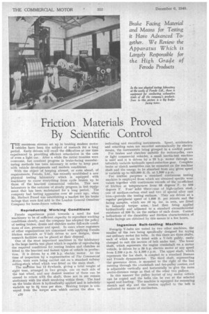
Brake Facing Material and Means for Testing it Have Advanced Together. We Review the Apparatus Which is Largely Responsible for the High Grade of
Ferodo Products
THE enormous stresses set up in braking modern motor vehicles have been the subject of research for a long period. Early drivers will recall the difficulties at one time experienced in providing efficient retardation in the case of even a light car, After a while the initial troubles were overcome, but constant progress in brake-facing manufaeturing methods has been necessary in order to keep pace with vehicle developments and modern conditions.
With the object of keeping abreast, or even ahead, of requirements, Ferodo. Ltd., has recently established a new physical testing laboratory which is equipped with machinery to cover everything from cycle brakes up to those of the heaviest commercial vehicles. This new laboratory is the outcome of steady progress in test equipment that has been maintained for a long period, The company had testing apparatus over 40 years ago, when Mr. Herbert Frood was establishing a Market for his brake facings that were first sold to the London General Omnibus Company for horse-drawn vehicles.
Reproducing Working Conditions Ferodo experiences point towards a need for test machinery to be of sufficient capacity to reproduce working conditions closely, and the company has adopted the policy of testing brakes, drums and clutches under full-scale conditions of size, pressure and speed. In cases where engineers of other organizations are concerned with applying Ferodo friction materials or V-belt drives to new designs, these research facilities can be placed at their disposal.
One of the most important machines in the laboratory is the large inertia test plant which is capable of reproducing the required conditions for testing brakes and clutches as fitted to the heaviest and fastest types of vehicle in production. It is driven by a 100 h.p. electric motor. At the time of inspection by a representative of The Commercial Molar, tests were being carried out on 'a standard railway rolling-stock wheel which was fitted on the main shaft.
The mathine has 12 flywheels, giving a total weight of eight tons, arranged in two groups, one on each side of the test wheel, and any desired number of these can be caused to rotate with the shaft; those not in use remain stationary with the shaft revolving within them. The load on the brake shoes is hydraulically applied and is infinitely variable up to 3i tons per shoe. Braking torque is coilveyed from the torque arm which carries the shoe to
indicating and recording instruments. Speed, acceleration and retarding rates are recorded automatically by electric means, the instruments being grouped in a control panel.
For brakes and clutches suitable for motorcycles, cars or light commercial vehicles, a small inertia-test machine is used and it is driven by a 25 h.p. motor through an infinitely variable hydraulic speed-reduction gear. Complete brake or clutch assemblies can be mounted on the machine shaft and the energy to be absorbed from any given speed is variable up to 810,000 ft.-lb. at 1,500 r.p.m. For routine purposes a standard continuous testing machine is emPloyed from which are obtained specific wear values together with continuous records of the co-efficient of friction at temperatures from 65 degrees' F. to 550 degrees F. Four solid discs—one of high-carbon steel, . one of medium-carbon steel and two of special alloy cast iron—provide the testing .surfaces. They ar_e driven at a regular' peripheral speed of 1,000 ft. per minute and the facing samples, which are 10 sq. ins, in area, are fitted in balanced torque arms, load then being applied hydraulically and adjusted to a standard circumferential resistance of 330 lb. on the surface of each drum. Correct indications of the durability and friction characteristics of brake facings are obtained by this means in a few hours.
Ingenious Belt-testing Machine Ferogrip V-belts are tested by two other machines, the smaller of the two being specifically designed for trying out ordinary motor fan belts. In this there are three shafts. each of which can be fitted with a V-belt pulley, easily changed to suit the section of belt under test. The lower shaft, which represents the enginecrankshaft on a motor vehicle, is driven by a 28 h.p. electric motor at any speed from 2,250 r.p.m. to 4,500 r.p.m. The upper shaft, which represents the fan shaft, is coupled to a standard Heenan and Fronde dynamometer. The third shaft, representing the generator drive, is mounted to the right of the line running through the crankshaft and fan-pulley centres. and is adjustable vertically and horizontally to give the same centre-distance range as that of the other two pulleys.
In this manner the pulley layout of any motor vehicle can be copied and the belts can be run at the selected speed and loading. The machine is equipped for measuring stretch and slip and the tension applied to the belt is indicated by means of statimeters.