


A Braking System for Trailers
Page 52
If you've noticed an error in this article please click here to report it so we can fix it.
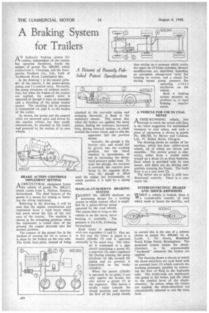
AN ydraulic braking system for trailers, independent of the tractor but operated therefrom, forms the subject of patent No. 600,949, which comes from L. Chouings, and the Automotive Products Co., Ltd., both of Tachbrook Road, Leamington Spa.
In the drawing 1 is the master cylinder of the tractor, 2 the power-driven pump, and 3 a control valve. Normally, the pump circulates oil without restriction, but when the brakes of the tractor are applied, the control valve is operated as though it were an expander and a throttling of the pump output occurs. The resulting rise in pressure is transmitted via pipe 4, to the brakes of the trailer.
As shown, the pump and the control valve are mounted upon and driven by the tractive vehicle, but they could, alternatively, be attached to the trailer and powered by the motion of its own wheels.
BRAKE ACTION CONTROLS IMPLEMENT SETTING
A GR1CULTURAL equipment forms rAthe subject of patent No. 600,217, which comes from L. Dufour, Geneva,. Switzerland. The chief feature of the patent is a means for raising or lowering the tilting implement.
Referring to the drawing, it will be seen that the engine, transmission andimplement form a rigid beam which can pivot about the axis of the rear axle of the tractor. The machine is shown in the ploughing position; when the implement is raised clear of the ground, the engine descends into the normal position.
The essence of the patent lies in the method of causing the tilt to occur; it is done by the brakes on the rear axle. The brake back-plate, instead of being attached to the rear-axle casing and swinging therewith, is fixed to the stationary chassis. This means that when the brakes are applied, the bevel pinion, finding the resistance increased, tries, during forward motion, to climb around the crown wheel, and so tilts the apparatus into the position shown.
Actually, the plough is the heavier unit, and would fall by gravity into the working position, but the bevel reaction is, nevertheless, of use in increasing the downward pressure under load. To raise the plough, the machine is reversed; the reaction now being in the opposite direc tion, the plough is lifted until the engine lies horizontally, in which position it is held by a spring catch.
MANUAL-CUM-SERVO BRAKING SYSTEM DATENT No. 600,902 discloses an 1 interesting design for a braking system in which manual effort is amplified by a power-driven pump operated by the road wheels. This means that so long as the vehicle is on the move, servo braking is available. The patentee is S.I.A.M., Fribourg, Swi tzerland, Each brake is equipped with two expanders (1 and 2). One set, in this case the lower, is piped to a master cylinder (3) and is operated manually in the usual way. The other set is connected to a pipe circuit containing a pump (4), a reservoir (5), and a regulator (6). During running, the pump circulates oil idly around the piping and no pressure is transmitted to the brake cylinders.
When the master cylinder is operated by its-pedaL it not only applies the brakes but also moves a piston (7) in the regulator. This moves a needle valve towards the closed position and .restricts the flow of the pump circuit,
thus setting up a pressure which works the upper set of brake cylinders. Several modifications are described, including an automatic change-over valve for braking in reverse, and a means for storing excess pump pressure for operating other auxiliaries on the vehicle.
Such a braking system presents no problem as to legal
braking requirements.
A VEHICLE FOR USE IN COAL MINES
A FREE-RUNNING vehicle, low rtenough to reach the actual coal face, is the latest suggestion for mechanized transport in coal mines, and such a piece of equipment is shown in patent No. 600,560, by Mayor and Coulson. Ltd., 47, Redan Street, Glasgow.
The drawing shows an outline of the machine, which has four rubber-tyred wheels, all of which are driven and steerable. The motive power is electricity, either from a trailed cable wound on a drum (1) or from batteries. Each wheel is provided with its own motor, and there are .no driving connections crossing the frame. The body floor is at a low level (2).
The driver sits at point 3, with twodirectional controls. There is a conveyor (4).
INTERCONNECTING BRAKES AND SHOCK-ABSORBERS WHEN a vehicle is braked, there is WY a considerable transfer of load which tends to lessen the stability, and
to correct this is the aim of a scheme shown in patent No. 600,642, by A. Lamb, 5, Fir Grove, Brentford Road, Kings Heath, Birmingham. The proposed system causes the shockabsorbers to be automatically "hardened" whenever the brakes are applied. The drawing shows a chassis in which the shock-absorbers are each fitted with an external lever (1) which controls the working resistance, possibly by restricting the flow of fluid in the hydraulic type. The brake-rods are duplicated, one going to the brake, and the other to the control lever of the shockabsorber. In action, when the brakes are applied, the shock-absorbers are automatically adjusted to suit the extra load.