


Indicating Engine Heat Losses
Page 36
If you've noticed an error in this article please click here to report it so we can fix it.
A Resume' of Patent Specifications That Have Recently Been Published. Copies May be Obtained from the Patent Office, Price 11each
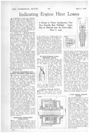
ACCORDING to patent No. 567,806, by 11. Ricardo, 21, Suffolk Street, London, S.W.], and G. Hempson, 4, Norham Gardens, Oxford, the rate at which combustion heat is dissipated through the cylinder walls forms a valuable guide to combustion conditions, and the patent describes an instrument by which this heat flow can be instantaneously measured.
It consists of a sparking-plug-like body containing a steel sleeve (1) and a central. wire (2). The sleeve is airspaced so far as possible from its surroundings, to reduce the reception of heat from its sides. The central wire, made of Constantan, is likewise insulated by a winding of asbestos string. At the lower end (3) the wire is silver-soldered to the sleeve to form a thermo-couple. The upper end is water-cooled, and is fitted with a second thermo-couple, not shown.
In operation, the two thermo-couples are wired to a milli-voltmeter which gives a differential reading proportional to the rate of heat flow along the steel sleeve, which is intended to represent, so far as possible, a piece of the cylinder wall. The inventors state that the device is specially helpful in detecting incipient detonation, because, before it actually occurs, there is a sharp rise in the meter reading. It is, therefore, ...possible to find the most economical working point just before the heat-loss curve rises steeply.
SURFACE TREATMENT FOR HIGHLY STRESSED COMPONENTS
TOimprove the durability of parts such as springs, transmission shafts, connecting rods and crank-pins, in fact any highly stressed working surface, is the object of a process described in patent No. 567,281, by A. Fobiette, 189, Monmouth Drive, Sutton Coldfield, Warwickshire.
The method consists of a surfaceheating operation by ' the highfrequency-induction method, followed, while the job is' still hot, by a coldrolling operation which may also, if desired, effect the final dimensioning to within close liniits. The rollers are made from hard material, such as tungsten carbide, and may be watercooled if-Jound necessary. A " pimpled " surface may be employed if a smooth surface be unessential, the aim being to give a peening effect and so produce a surface containing a multiplicity of compressive stresses:
The scheme may be applied to complex shapes such as gearwheels; in this case the roller is a hard gear, as near perfect as possible, and is heavily loaded while running in mesh with the heated workpiece. • IMPROVING PISTON-RING LUBRICATION
THE underside of a piston ring is always inclined to go short of lubrication on account of the squeezing-out action of the high gas-pres-ure a:Dove it. To provide a slight lifting action on each cycle to permit the entry of oil is the object of a scheme shown in patent No. 566,787 by R. Thomas, 59, South Avenue, Shelton, Lock, Derby. 'The drawing shows a piston ring (1) of normal shape, with the addition of a special spring-ring (2) underneath it. The latter is of conical form in its fiee state, but when in place is pressed into a nearly flat outline. Under combustion pressure it is completely flattened, but on the upstroke it lifts the piston ring slightly and so sets up a pumping action which draws in oil on the underside.
AN EASY-TO-READ TYREPRESSUR E GAUGE THE usual tyre-pressure gauge has its graduations arranged helically around the stem, in order to find room for the figures in the small space available. An im proved 'type, claimed to be easier to read, forms the subject of patent No. 567,320, from .W. Turner, 44, Eyre Lane, Sheffield. In this design, the graduations are grouped in tens, and each fifth one only is numbered, the others being easily estimated. To help still furthef, the top edge of the body portion is made in a coloured plastic material.
A NOVEL TYPE OF CLUTCH
PATENT No. 567,265 comes from R. G. Letourneau Inc., Peoria, Illinois, U.S.A., and describes a power
operated clutch, the actuating mediuir being compressed air. Although no! described as being applicable to motoi vehicles, the principle is sufficient13 interesting to note, especially in thesc days when the increasing size o vehicles approaches the limit o unassisted manual control.
In the form shown, the central shaf is, say, the driving member, whilst On driven member is the outer casing Two opposed cones are used, sliding OT the splined shaft and held out o engagement by a number of spring (1). The left cone is fitted, with a pro jectiug flange (2) which closely fits recess in the other cone and forms ai annular piston, the fit of which i assisted by cup washers at all slidim faces. A supply of compressed ai arrives via a bore in the shaft and passing through cross-holes (3), reache the expansion space (4) , where i separates the two cones and force their friction facings into driving con tact with the casing. No adjustmen is necessary during the life of the fac ings, wear being accounted for by ; slightly increased sliding movement.
A BUS TICKET ISSUING SYSTEM
A TICKET machine for use b.
bus conductors forms th subject of patent No. 567,262 from F., J. and A. Williamson "Moorlands," Mottram 01 Road, Stalybridge, Cheshire. 1 single loose pack of tickets i employed, the tickets being pia printed with a line of progressiv fare prices. -When a ticket i inserted into the machine b hand, the price strip is snippe off at the appropriate point, an the removed portion falls into box where it is storedfor checli ing purposes. The machin prints the stage number in th inward or outward direction t. the journey, and can be arrange to print the date; the settings k these are performed by means c. external discs: