


WHAT ARE THE CHANG )R FRAMELESS VEHICLES?
Page 26
Page 27
If you've noticed an error in this article please click here to report it so we can fix it.
Considerations of Frame Distortion in Orthodox Designs. Difficulty of Spreading Intense Localized Stresses in Chassisless Construction
FOR many years past the commercial-vehicle industry, as a whole; has shown keen interest in the development of chassisless vehicles, 'some manufacturers having experimented with their construction. In theory, a van or bus body is an almost ideal shape for supporting weight, being a continuous box-section, but, in practice, no really satisfactory results, in the form of a completed vehicle weighing less than one of orthodox design, have, to date, been achieved.
Before the problems confronting the chassisless-vehicle designer can be discussed, it is imperative that the stresses induced on a vehicle, under normal operating conditions, be appreciated. This can best be accomplished by studying road action on a loaded, orthodox frame. , When a vehicle is travelling along a road five different reactions on the frame are possible. One wheel of one axle can strike a bump Or pothole, the other three wheels being unaffected; both wheels of an axle can strike an obstacle simultaneously; two wheels on the same side of the vehicle can encounter an obstruction at the same time; two wheels, one on each axle at opposite sides of the vehicle can be • affected, or all the wheels may strike at once. In addition, braking stresses, and those due to centrifugal force, can be applied to the frame. .
In order to accommodate these stresses the frame side. member, which is assumed to take all loads with the exception of twist, as no satisfactory method of stressing cross-members has yet been devised, is given a factor of safety of 4 to I. That is, after the stresses induced by static loading and braking forces have been calculated, the side-member is made so that it will withstand four times this stress before breaking.
A figure of 4 to I may, at first sight, appear to be on the high side, but if the additional stresses set up by striking obstructions, as already outlined and which cannot be accurately calculated, be taken into account, it will be appreciated that such a factor of safety is none too high.
Forces that Encourage Lozenging.
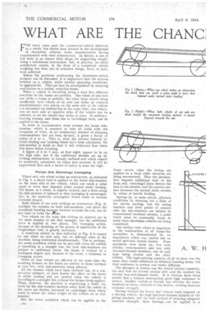
Where only one wheel strikes an obstruction, as indicated in Fig. 1, a shock load is applied to the frame side-member on the same side of the vehicle, which can reach a value equal to twice that imposed under normal static loading. The frame, as a whole, is slightly twisted, and a force along the side-member is induced so that lozenging is encouraged, that is, the naturally rectangular frame tends to become diamond shaped.
Both wheels of one axle striking an obstruction (Fig. 2) multiply the stresses on both side-members, and move the maximum bending momInt forward towards the cab, but do not tend to twist the fnme.
Two wheels on the same side hitting an obstacle act in the same manner as our first example, but the additional force is applied in two places. The lozenging action, because of the doubling of the points of application of the 'longitudinal load, is greatly increased.
A condition similar to that indicated in Fig. 3 is caused by one wheel on each axle, but on different sides of the machine, being obstructed simultaneously. This is, perhaps, the worst condition which can be met with when the vehicle is travelling in a straight line, for both side-members are subject to additional stress, the frame is twisted to a maximum degree and, because of the twist, a tendency to lozenging occurs.
When all four wheels are affected at the same time the resulting stresses on the frame are similar to those outlined in case. two, both side-members being affected.
All the stresses which have been outlined can, at a conservative estimate, at least double the effect on the frame of static loading and are exerted when the vehicle is travelling in a straight line without the brakes being applied. When however, the machine is negotiating a bend, the loads on the side-member farthest away from the centre of the curve are further increased by centrifugal force which tends to throw the whole weight of the vehicle on to that member.
But the worst condition whicli can be applied to the
frame occurs when the brakes are applied on a bend while obstacles are being encountered. Here the deceleration imposes additional load at the front end, centrifugal force throws the load to the outside, and the uneven surface increases the normal static .stresses by virtue of inertia loading.
Springs do, to some extent, alleviate conditions by damping out a little of the inertia loading, but the spring brackets and their points of contact with the side-members are subject to concentrated localized stresses, a point which must be constantly borne in mind when chassisless vehicles are being considered.
One further item which is important in the construction of all frame-like assemblies is demonstrated by an experiment which was carried out on model grid-iron chassis frames. Four specimens were made up, two with tubular cross-members and two with box-and-channel members, one of each type being riveted and the other welded. The load-carrying capacity of all of them was the same; they would withstand an identical bending stress, but their resistance to torsion was vastly different. The strongest in torsion was the welded tubular assembly, the next ivas the riveted tubular unit, and the weakest the riveted box-and-channel frame. It is obvious from these results that a tubular construction gives high resistance to torsion, whether welded or riveted, but whether the crossmembers be tubes, channels or box section, welding increases torsional strength.
Having realized the heavy and various loads imposed on a moving vehicle, the high localized stresses induced at the spring brackets, and the hest method of ensuring adequate torsional strength, these findings, can be applied to a
A. W. H
theoretical frameless type of vehicle.
The machines most suited to chassisless construction are, vans and buses. Whilst platform lorries cannot be entirely ruled out (the underframing of the body which is normally mounted on the orthodox frame could form a basis for construction), the provision of a suitably strong skeleton on which to . mount the various chassis units would merely be substituting a complicated structure for one which is the acme of Let us, therefore, consider the manufacture of a. single-deck bus.
Defined in 'simple terms, such a vehicle is a rectangular box mounted on wheels, ths front axle being placed at the extremefront of the machine, whilst the rear axle allows considerable overhang. The box, despite window and door openings, would be of adequate strength with regard to simple
. A.M.I.A.E, support of the load, and could be made
highly 'resistant to torsion by the incor poration of tubes in the floor construction, and by corner bracing and welding of the complete structure. The all-metal construction would be in a light alloy, or steel, or a combination of both.
I3ut the support of load and resistance to torsion are incidental to the design, their achievement being straightforward. It is the attachment of the axles, in particular, and the spreading of the intense localized stresses over a more or :ess flimsy structure, which constitute the real problems.
If the orthodox position of the front axle is to be main tained, the engine cannot be located at the front. The tubular construction of the underframing would foul the power unit and necessitate its removal to a more suitable location, preferablyamidships under the floor where it
could not interfere with other units and yet would still be accessible and easy to control.
The question of front-end accessibility would not, therefore, arise, and two tubular members could be fitted-across the vehicle on which the springs would be mounted, These tubes would necessarily be twice the length of orthodox crass-members and, where they joined the main framing. would require specially spread fixings in order to prevent localized stresses. (Fig. 4.) • Similar mounting of the rear axle would ensure that the weight of the vehicle and additional dynamic loads were accommodated by strong members attached to the body in such a way that distorting stresses were distributed over a wide area.
The engine and gearbox assembly, assuming unit construction, would be supported on light channel-section members. This could be accomplished in a similar manner to that employed by Leyland Motors, Ltd., on a fleet of flat-engined coaches. Engine mounting was two-point, and consisted of a large rubber ring at the rear, securely clamped to the casing and its own bracket, so that it could withstand driving torque, and a simple T-support at the front, which •enabled the engine to roll on starting, and to And its own balance during runnings Such an engine mounting is particularly suitable for frameless construction, for, apart from the extreme simplicity of the two-point suspension system, the power unit is statically balanced. This condition is ensured by so arranging the supports that a line drawn through their centres also passes through the centre of gravity of the engine. Thus, when the Unit is started, although it rotates through an angle in the region of 10 degrees, due to the initial torque, no unbalanced forces, which would cause vibration and tend to induce fatigue in the construction material, are applied to the supporting framing while the engine is running.
Relocation of Engine Necessary
Identical arguments to the foregoing could be used for vans and double-deck buses but, in each case, it would be necessary to relocate the engine and, for the double-decker, to provide extra framing for supporting the rear platform. Were the engine left in its orthodox front position, the outlook for frameless construction would be far from rosy, and it is, perhaps, for this reason that, to date,' no apparent progress has been made in this country.
The methods of approach employed in the past have been based on the use of sub-frames, on which the axles, engine and gearbox have been mounted. Some years ago the White Coach Company, di America, manufactured a vehicle on these lines, but it appeared to be constructed of small plates and pressings welded together. It was rather too messy in appearance.
Such attempts would seem doomed to failure at the outset for, assuming a flat-engine construction, which is the most suitable, it is necessary to provide ,three separate sub-frames which occupy almost the entire length of the vehicle. The sub-frames must also be well braced and well supported on the main framing, which mean increased weight and cost.
If, then, these units occupy so much space and, as has been proved by actual experiment, save no weight, there is no object in replacing the orthodox frame. But the method of construction here outlined would not add complication to the orthodox unit and .would save weight and probably cost, two factors which are of paramount importance in the production of all road-transport vehicles.
Design in the past few years has becoMe stereotyped. " Production " has been the all-important watchword and; wherever it has conflicted with ideal design, it has won the day, the best possible layout taking second place to one which would give satisfactory-results, because it was easier to produce.
This attitude, fostered by the necessities of war, will not always obtain, and it is hoped that the more enterprising of out manufacturers will once more take up the development struggle in post-war years, and produce a really satisfactory frameless vehicle which costs less, is lighter, and is easier to service than existing orthodox machines.