


Abridgments of Interesting Patent Specifications.
Page 20
If you've noticed an error in this article please click here to report it so we can fix it.
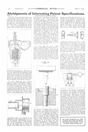
Scott, No. 28,644, December 29th, 1904—A vaporiser of the surface type is described in this specification, having a fue/ inlet valve (F), the amount of movement of which can be regulated by a screw. threaded sleeve (H) controlled by a spring (G). The valve is automatically opened by a larger spring-controlled valve (J), which rises by the suction of the engine
and strikes the sleeve (H). The fuel nos 21e (E) is surrounded by wire gauze (I,) and wick (M), which dip into the surplus fuel which collects at the bottom of the cham• ber, and the chamber is surrounded by a jacket (B), so that the air previously heated and admitted by the inlet (A) raises the temperature of the whole vaporiser.
No. 5,819. March 9th, 5904. "Carburetters for internal Combustion Engines." William Poland.—The inventor employs the well.known Bourdon vacuum or pressure tuba to operate one or more valves or equivalent to regulate the main or the supplemental air inlet or both. It will be appreciated that the tube may be intro. duced at any desired part of the carburetter or carburetting system, but one way —especially where it is applied to the regulation of the supplemental air—is to take an Ordinary vacuum gauge and connect the vacuum pipe to some suitable part of the carburetting or suction system of the engine and to extend the spindle of the index hand and connect it with the valve controlling the supplemen tal supply of air. This may be conveniently arranged by applying the back of the vacuum gauge (A) to a horizontal branch (D) of the carburetter in or in connection with which is a disc air valve (C) preferably of the hit-and.miss type, so that as the spindle of the vacuum gauge is turned it turns the perforated disc, thus opening the additional air supply which automatically closes when the suction is reduced by the spring of the vacuum gauge. The vacuum tube can be used and connected without the assistance of a registering needle or recording device of any kind ; nevertheless, it is sometimes advantageous to have the gauge, as it enables the suction of the engine to be ascertained at any moment. A dash-pot mechanism may be employed, if desired, in connection with the gauge so as to obtain a steady reading.
No. 10,355, May 5th, 1904. "Axle Barrels for the Wheels of Road Vehicles." Hugh Myddleton Butler—Axles for the wheels of road vehicles are usually forged in a piece with the barrels, and the latter have occasionally been lightened by drilling or otherwise forming a central aperture inwardly from the extremity so as to make the barrel portion hollow, and the ends of the holes thus bored have been filled in with screw plugs, so as to prevent the entrance of foreign matter, and for the purpose of strengthening the extremity of the barrel where it is required to insert a pin for retaining the wheel in position, or to apply other fixing device. Now, according to this invention, each barrel is made separately, being formed from a single stamping or forging, and consists of the barrel proper (1) with an enlargement (2) at its inner end, and from this enlargement a flange (3) homogeneous with the barrel is produced by upsetting, or other suitable means, thus leaving the ordinary collar with the flange beyond, by which latter the barrel so constructed can be attached to any axle treeor bed or other support. Preferably during the manufacture the interior of thebarrel is hollowed out at 4 from the centre of the flange so as to make the barrel tubular, but with a closed external end Fig. i is a vertical section showing the barrel formed with a flange, Fig. 2 being a right-hand end view, and Fig. 3 a lefthand end view of the barrel, Fig. 4 as a sectional elevation showing an example of dies for forming such a flange as is shown at Figs. TO 3. In some cases, instead of the parts 3 being formed as flanges, they may be formed with extensions to produce, for instance, steering pivot pins. in a piece with the barrel.
Robin, No. ii,o4;, January 19th, 1905. (dated January 23rd, 1904).—In place of springs for absorbing vibration between the wheels and road vehicle bodies a pneumatic device is employed according. to this invention. The road wheel axle (r) is carried between vertically-guided cross heads connected at each end to a plunger ii), free to slide in a piston (j) working in a cylindrical chamber (f). The chamber is connected with a reservoir (c.) charged with air under pressure, and vi. brat ion is absorbed by the piston (j) rising and falling in the chamber (t) against the air pressure. An oil seal is provided at the bottom of the chamber (f), and this also operates as a dash-pot for the head (j1) of the piston. The plunger (i) moves separately in the piston for the purpose of following the axle when the road wheel drops into a declivity in the road surface. The great advantage of this device is that the air pressure at all times is almost constant as the area of the piston and plunger is small compared with the area of the reservoir (c). The piston is prevented from colliding with the upper end of the cylinder by omitting the perforations (p) in this part, so that a body of air is trapped and arrests the progress of the piston. A suction valve (q) is placed at the top of thecylinder to admit air from the reservoir as the pistons returns after having entered this end portion.