


A Daimler-Benz Automatic Gearbox
Page 56
If you've noticed an error in this article please click here to report it so we can fix it.
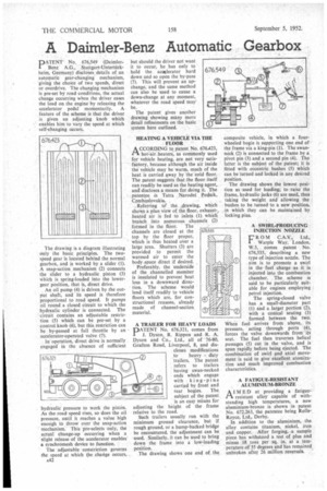
PATENT No. 676,549 (DaimlerBenz A.G., Stuttgart-Unterttirkbeim, Germany) discloses details of an automatic gear-changing mechanism, giving the choice of two speeds, direct or overdrive. The changing mechanism is pre-set by road conditions, the actual change occurring when the driver eases the load on the engine by releasing the accelerator pedal momentarily. A feature of the scheme is that the driver is given an adjusting knob which enables him to vary the speed at which self-changing occurs.
The drawing is a diagram illustrating only the basic principles. The two. speed gear is located behind the normal gearbox, and is worked by a slider (I). A snap-action mechanism (2) connects the slider to a hydraulic piston (3) which is spring-loaded into the lowergear position, that is, direct drive.
An oil pump (4) is driven by the output shaft, and its speed is therefore proportional to road speed. It pumps oil round a closed circuit to which the hydraulic cylinder is connected. The circuit contains an adjustable restriction (5) which can be pre-set by a control knob (6), but this restriction can be by-passed at full throttle by an accelerator-operated valve (7).
In operation, direct drive is normally engaged in the absence of sufficient
hydraulicpressure to work the pistetn. As theroad speed rises, so does the oil pressure, until it reaches a value high enough to throw over the snap-action mechanism. This pre-selects only, the actual change-up occurring when a slight release of the accelerator enables a synchromesh device to function.
The adjustable constriction governs the speed at which the change occurs, A42 HEATING A VEHICLE VIA THE FLOOR
ACCORDING to patent No. 676423, hot:air heaters, as commonly used for vehicle heating, are not very satisfactory, because although the air inside the vehicle may be warm, much of the heat is carried away by the cold floor. The patent suggests that.the floor itself can readily be used as the heating agent, and discloses a means for doing it. The patentee .is Tatra Narodni Podnik, Czechoslovakia.
. Referring to' the ,drawing, which shows a plan view of the floor, exhaust-, heated air is fed to inlets (1) which' branch into numerous channels (2) formed in the floor. The channels are closed at the top by the floor proper, which is thus heated over a large area. Shutters (3) are provided to permit the warmed air to enter the body space direct if desired.
Preferably, the underside of the channelled member is insulated to prevent heat loss in a downward direction. The scheme would lend itself readily to vehicle floors which are, for constructional reasons, already made of channel-section material.
A TRAILER FOR HEAVY LOADS DATENT No. 676.321, comes from 1 I. Dyson, R. Rippon and R. A. Dyson and Co., Ltd., all of 76-80, Grafton Road, Liverpool, 8, and discloses modifications
to heavy duty trailers. The patent refers to trailers having swan-necked ends which engage with king-pin-s carried by front and rear bogies. The subject of the patent is an easy means for adjusting the height of the frame relative to the road.
Such trailers usually run with the minimum ground clearance, but if rough ground, or a hump-backed bridge be encountered, the adjustment can be used. Similarly, it can be used to bring down the frame into a low-loading " position.
The drawing shows one end of the
composite vehicle, in which a fourwheeled bogie is supporting one end of the frame via a king-pin (1). The swanneck (2) is connected to the frame by a pivot pin (3) and a second pin (4). The latter is the subject of the patent; it is fitted with eccentric bushes (5) which can be turned and locked in any desired position.
The drawing shows the lowest position as used for loading; to raise the frame, hydraulic jacks (6) are used, thus taking the weight and allowing the bushes to be turned • to a new position, in which they can be maintained by locking pins.
A SWIRL-PRODUCING INJECTION NOZZLE R 0 M C.A.V., Ltd.,
Warple Way, London, W.3, comes patent No. 676,535, describing a new type of injection nozzle. The aim is to promote a swirl in the fuel charge as it is injected into the combustion chamber. The scheme is said to be particularly suitable for engines employing petrol injection.
The spring-closed valve has a small-diameter part (1) and a larger portion (2), with a conical seating (3) formed between the two. When fuel arrives from above, its pressure, acting through ports (4), forces the valve downwards from its seat. The fuel then traverses helical passages (5) cut in the valve, and is spun rapidly before being ejected. The combination of swirl p.nd axial movement is said to give excellent atomization and much improved combustion characteristics.
A FATIGUE-RESISTANT ALUMINIUM-BRONZE AE D at providing a fatigue-. resistant alloy capable of with-standing high temperatures, a new aluminium-bronze is shown in patent No. 672,263, the patentee being RollsRoyce, Ltd., Derby. In addition to the aluminium, the alloy contains titanium, nickel, iron and copper. After forging, a sample piece has withstood a test of plus and minus 18 tons per sq. in. at a temperature of 35 degrees and has remained
unbroken after 26 million reversals. '