


HINTS ON MAINTENANCE.
Page 28
Page 29
If you've noticed an error in this article please click here to report it so we can fix it.
How to Get the Best Out of a Vehicle, to Secure Reliability and to Avoid Trouble.
CONTRIBUTIONS are invited for this page from fleet managers, drivers, garage foremen, and mechanics, works staff and draughtsmen, and will be paid for on a generous scale. Every system, make, and type of commercial motor vehicle will be dealt with, and the matter should be written with a view to the disclosure of workshop and garage practice in the maintenance of a vehicle—practices which, whilst they may be quite normal, are peculiar to the particular vehicle and may not be generally known to those responsible for its running. Expedients and suggestions for overcoming roadside and other troubles are covered in the following page, dealing with letters from our driver and mechanic readers. Communications should be addressed to " The Editor, The Commercial Motor, 7-15, Rosebery Avenue, London, E.C.1."
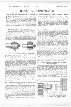
259.— Fitting Double-thrust Ball Bearings.
Double-thrust ball bearings are always employed where a shaft is subject to end thrust in both directions, also for skew-driven camshafts, pumps and rr.agneto drives, and large examples in the worm shafts of back axles. The illustrations show two methods of mounting these bearings, and it cannot be too strongly emphasized that they need most careful fitting. The nut (B) must be tightened hard home and secured with a split-pin. On no account must the bearing be adjusted by leaving the nut slack, for, even though it is pinned, it will fret on the thread and eventually strip it.
Referring to the illustrations. In Fiz. 1 the method adopted is to use a packing washer (A), the correct adjustment being obtained by varying the thickness of this washer. When the nut is tight, the packing should be of just sufficient thickness to allow the centre race to revolve freely, but without shake.
In Fig. 2, the bearing is mounted on a sleeve, which slips over the shaft, and is held by a nut, as in Fig. 1. The two outer races are a tight fit on this sleeve, the length of the latter deciding the adjustment. It is usually made a shade too long, and filed or ground Dff when the bearing is mounted on it, but great care must be taken that no filings get into the bearing. It will be understood that the shaft is located in position 'by a cover or cap, which grips the centre race (R), but the bearing must be fitted before the shaft is put in its place in engine or axle, although it will, of course, have to be slipped off again temporarily for that. purpose.
260.—Fitting Oil Baffle Plates on Thornycroft Engines.
We have on several occasions published methods of fitting oil baffle plates on Thornycroft engines, but these have involved dismantling the cylinders and everything surrounding them. The following method has been employed on each vehicle of a fairly large fleet and has proved quite satisfactory, the work involved being only a fraction of that required by the cylinder removal method, The one disadvantage is that the use of a pit is almost essential ; at the least, it is very desirable, but a pit can usually be found for the job.
The sequence of operation is as follows :—Remove c44
the undershield, then the oil pipes from the priming box to the filter in the base, also the one on the near side of the engine which leads from the oil pump to the three plugs opposite the main bearings. Drain the oil from the base, remove the filter, and then the bottom half of the base chamber.
Now comes the most difficult task. This is the removal of the four centre cylinder studs, which have to be replaced by new ones supplied with the baffle plates. Some of these studs usually come out quite easily, but now and again one or more may be extremely difficult to extract. A method which has seldom failed is to fit a nut on the stud and drill through the nut half-way into the stud. Into the hole thus made fit a ?E-in. grub screw, then apply an ordinary spanner.
Once the studs are removed; the task is simplified. Cut a corner off each front plate according to requirements, and bend the sides of the plates as may be necessary to ensure a snug fit. When in position, turn the flywheel and make certain that the four connecting rods clear the plates at all points. Replace the base chamber, oil pipes and undershield, and the task is completed.
The cost of this operation is soon repaid by the reduction in the consumption of lubricating oil, which in the last successful cases is said to be 50 per cent., and in the majority of eases 75 per cent.
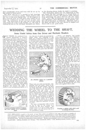
261.— Curing Rattle in Timing Case of 50 h.p. Earlier Engine.
Rattle sometimes develops in the timing case of the 50 h.p. Karrier engine owing to float of the magneto driving shaft. The camshaft of this engine is driven by an extra wide silent chain from the crankshaft. Immediately behind the chain sprocket on the camshaft is a smaller spur wheel, which engages with the magneto driving shaft pinion. If end-play occurs on the magneto driving shaft the pinion is allowed to move forward and then comes into contact with the rivet heads of the silent chain.
Apart from the rattle caused, it will be obvious that considerable stress and wear will be set up by the contact of these parts. The shaft referred to is carried in ball bearings housed in a. cylindrical easing, which projects from the rear of the main timing case. If the magneto is first removed from its base plate this casing can be freed for withdrawal by the removal of four nuts only. The detaching of the rear cap of" this casing will expose the cause of the trouble, i.e., the lack of locking devices on the left-hand threaded -nut which, as the drawing shows, holds the shaft in position.
The illustration shows how the tightening of this nut causes the ball bearings to be forced home in their respective recesses, the distance collar between them gOverning the ,space between the -two inner races. After this all-important nut has been tested and tightened, a hole should be drilled parallel wit', the axis of the shaft, as indicated. This hole, half in tho shaft and half in the nut, should be tapped and fitted with a I-in. grub screw.