


How to Line-up an Engine.
Page 29
Page 30
If you've noticed an error in this article please click here to report it so we can fix it.
By an Engineer-in-Charge.
The correct alignment of the engine in a steam wagon or tractor is a very important item; firstly, on account of the extra friction set up in the various working part, thereby necessitating the use of extra coal and oil, and secondly, owing to the increased wear and tear which is continually taking place if all parts of the engine are not in line; both are serious items to the owner and are the cause of trouble and anxiety to the driver. I
I have known several instances where the engines have not been in alignment, and in one instance, to avoid overheating, the bearings had to be run so slack that the engine was practically knocking itself . to pieces; directly anything was tightened up, overheating commenced. The driver marked that " it always had been so since he had been with it, and supposed it always would be." After -a trial run, I concluded that the engine was out of line, and any doubts were soon dispelled, for, on looking through the tool box, I discovered several liners that had been taken out at some previous time.
The term "out of line " means that the crankshaft is not exactly at right angles, or square, with the centre line of the cylinder; it may be out both lengthwise and cross+ wise of the engine, and this may arise from several causes In the majority of cases, it is due to wear, or to the indisl cricninate use of liners, or probably both, and, although th remedying of this defect may seem a big job to some men . it is, in reality, very simple to a man who is capable of exer cising care and judgment. , The first thing to be done is to disconnect the engine by taking off the connecting rod and eccentric rods, and care.fully to note the position of any liners in the crosshead or big end of the connecting rod. The gland packing should then be drawn, and replacing the gland, it should b I screwed down tight against the stuffing box. The pistol rod should be driven olf the cresshead and pushed back ii the cylinder. Then the crosshead should be tried for slack-. ness at each end of the guides,it is most likely to have worn more in the centre of the bars than at the ends; this can easily be found with a pair of inside callipers. The two bottom bars should then be taken off and filed squarely: across the faces until they show fair with a straightedg when placed lengthwise. The bars should now be replace and, if everything has been,done satisfactorily, they shoul be parallel for the whole..length, so that by placing tw temporary liners tinder the Shoes (just sufficiently to brin them up to the top bars) they should be a nice free fit al along.
Now, the crosshead should be pushed back towards the piston rod, and it should he noted how the taper on the rod corresponds with the tapered hole in the crosshead ; at the same time it should be seen how the rod looks in the gland (which should have been slackened out and tried, to make sure that it is quite free and not binding in the stuffing hex). The gland should be replaced, the crosshead drawn oil the rod, and pushed along to the opposite end, bringing the piston rod up to the opposite end of the stroke, and again try for alignment. If it is found that everything is free, an amount must be filed off the bottom bars equal to the thickness of the liners under the shoes. On the other hand, it may be found that the rod is not quite fair and very likely more would have to be taken off one end of the bars than off the other, so that it becomes necessary to insert paper liners under the tap bars to bring them parallel. It is in 1 case like this where the exercise of judgment is required in order to get the crosshead a working fit along the bars and the gland free on the rod and in the stuffing box at am part of the stroke. The bars should now be tried with straightedge laid crossways over the two bars, to mak sure that the filing has been done correctly.
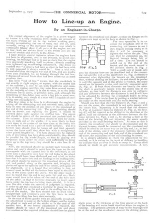
In the case of bored guides with an adjustable crosshead, the adjustment is made on the bottom slipper, and by trying the gland at each end of the stroke as in the case of th , parallel bars. If any lateral adjustment is required, the slippers should be taken off the crosshead pin and sheet iron washers of the required thickness should then be place between the crosshead and slipper, so that the flanges on tint slippers are kept up to the bars as shown' in Fig. 1.. The next operation is to ex. amine the crosshead end of fin connecting rod brasses to see ii they require cutting back; to dc this it will be necessary tc tighten the rod on the pin. They can then be connected up, thE big-end brasses being left of for a time. The rod should Ix pulled out to the end of thE stroke and the crank turned ir the position shown in Fig. With a small pair of inside earn pers the distance between the machined end of the connect. ing rod and the web of the crankshaft (A, Fig. 2) should b( measured after tightenihg the brasses on the crosshead then, without shifting the callipers, the rod should be pusher in until the opposite end of the stroke is reached, the cranli turned on its opposite centre and carefully measured agair (A, Fig. 3). If both these.clistances are exactly the Same the shaft is practically square with the centre line of thE cylinder, so that both the distances can now be calliperec and any differenee between the distances A and B will hay( to be adjusted by shifting the crankshaft bodily to bring them equal. This can be done by putting a washer between the collar on the crankshaft and the main bearing.
Should you find that the two distances (A, Figs. a and 3' are not the same, the crankshaft is not quite square with the centre line. Supposing it is found that the distance (A, Fig. 2) is greater than the distance (A, Fig. 3), the bearing (C) will be required to be shifted in the direction of thE *row, half the thickness of the difference between the distance between (A, Figs. 2 and 3), by placing a liner at the back of the bearing (C) and adjusting the screw usualb; provided in the main-bearing brackets. AS soon as this is correct, the crosshead end should be disconnected and the big-end brasses should be connected up; the crosshead end should be tried in the same way as the big end, i.e., at botlends of the stroke, and if the distances between the small end of the connecting rod and fork end of the crosshead are tkite same, the adjustment of the main bearing is correct.
it is always advisable to check the adjustment by this method, as it is owing to the want of delicacy in handling the callipers that an error is likely to creep in. Every effort should be made to get accurate measurements. A verti
32/4Fi
slight error in the thickness of the liner placed at the back of the bearing will make itself manifest when the engine is running. The greatest amount of wear in the bearings will be at the end of the crankshaft nearest the driving pinion, .nd if it is required to bring that end of the shaft round at .11 and the liners will not permit it, it may be advisable to everse the brasses. I should have mentioned that the main earings should be carefully adjusted before carrying out he operation of alignment, and while the crankshaft is free ; .therwise, if they have to be let together after alignment, it nay throw the shaft out of line again.
The squareness of the crankshaft across the engine can low be found in an exactly similar way as described for quaring it up lengthwise ; only, instead of the crosshead wing placed at either end of the stroke, it should be placed n the centre of the guides. The crankshaft should be tried Lt half stroke, both top and bottom (Figs. 4 and 5), the rosshead bearings being tightened up until they are just ilack enough without any play. It will most likely be found :hat the fly-wheel side is down, or, that the distance (B, Fig. 4) is less than B (Fig. 5), so that a liner would have to )e placed under the fly-wheel bearing equal to half the dis:ances between B (Figs. 4 and 5) until both the distances :B) are equal. It is not advisable to lower the pinion end of the shaft to bring it level, for the teeth in the pinion will proably engage too deeply with the second-motion shaft wheels, %rid the result will be excessive noise. The eccentric rods
can now be coupled up and tried to see how the forked ends come to the links ; it will generally be found that they require a little adjustment to bring the forked ends fair with the links. This is accomplished by shifting the eccentric sheaves along the shaft, provided they are not turned solid with the crankshaft, which is now the common practice on this class of engine. In that case, the eccentric straps will have to be scraped so as to bring the rods quite free. The two half straps will have to be scraped on opposite sides; remembering that it will not require much scraping to allow a comparatively long rod to go over 1-32 inch. The same remarks apply to the connecting rod. When finally connecting up the big-end brasses, it should be carefully noted how the square end of the connecting-rod comes in relation to the back of the brass ; provided everything has been carried out correctly, they should butt nice and squarely with each other ; failing this, you will know that some error has crept in or sufficient care has not been exercised. If it is onlya slight amount out, a little judicious scraping will probably put matters right. When satisfied that everything is all right the engine should be coupled up again and the crankshaft should be pulled round several times to make sure it is quite free. If the shaft has been shifted in either direction, it is advisable to ascertain if the cylinder clearances are the same. They may require adjusting and, if the guide bars are properly marked, it is a simple matter to bring the crosshead back to its original position by shifting the liners. I have often found quite an assortment of liners at the back of brasses which have been put in at different times ; when the engine is being overhauled it is advisable to take these liners out and substitute one equal to their combined thickness. Great care should be taken to see that the slide-valve is in its correct position, as this is very itnportant and, if there is no exterior record of the position of the slide-valve, it is advisable to remove the steam-chest cover and adjust the valve if necessary. The engine should next be run fca—a little while, and all the bearings should be carefully watched ; any bearing that shows signs of heating will give trouble, it should, therefore, he locked at once.
The bearings will require constant attention for the first few days and should not be stinted for oil in any way; the extra care given to them at this time will be amply rewarded later by the smooth and easy running of the engine.