


A NEW BRAKE GEAR.
Page 52
If you've noticed an error in this article please click here to report it so we can fix it.
A Resume of Recently Published Patents.
A novel and -ingenious type of expanding brake has been patented by R. Schmitz, who, according to the patent specification, which is numbered 149,902, is an American citizen. In a preamble to his description of this device, be draws attention to fairly well-known drawbacks in connection with the usual type of brake, inasmuch as it wears unevenly, arid very often, after a time, owing to' the springs losing their elasticity, the Shoes are apt to come in contact with the sleeves of the drum; this causes a continuous drag upon the car, involving a loss of power and an increasedsconsumption of fuel. Be aisi points out that the effective operation of such a brake depends upon aconsider. able pressure being exerted upon the foot pedal or hand lever which controls it.
In the construction, which is the subject of his invention, be claim that the mechanism is Such that it can be entirely. enclosed within -the drum, so that it is almost self-acting after the shoes have been forced into contact with the drum lay pressure upon the brake pedal. At the same time there is no risk of seizure, The wear of the shoes, too, he claims, is practically . uniform "throughout theit length. Pinally, the withdrawal of the' shoes from contact with the Arum is posi. tively assured, and is not dependent upon any internal springs or similar device. As shown in thedrawing accompanying the specification, the shoes are four in number. They are &spired at equal distances apart insicle.the drum, and each is pivoted at one end. gad' shoe i3 attached to a plate parallel fo the wheel, and in that Plate a slot is cut, the direction of the slot, bring, when the shoe is in the fully 'withdrawn pbsition, as shown in the drawing, practically rad'al. Rollers fit into each-of these slots., and each.rolIer 'is supported by a-pin. The pins are all secured to' smini-plate mounted freely on the axle, the-lever °Ole cam , plateserving as an attachment-to the couptine rods from the brake'Pedal Or side brake lever. Movement of the cam plate under the influence of the brake pedal or lever involves movement of the 'rollers, and thus; owing to the shape of the slots:in the plates, the brake shoes are caused to engage with the drum. Moreover, as theslots are radial and the movement of the roller is -necessarily circumferential, this means that the first, portien of the movement of the shoes is comparatively rapid, but when due to engage movepient is slow, 'and therefore the engagement is gradual.
A New Spring System.
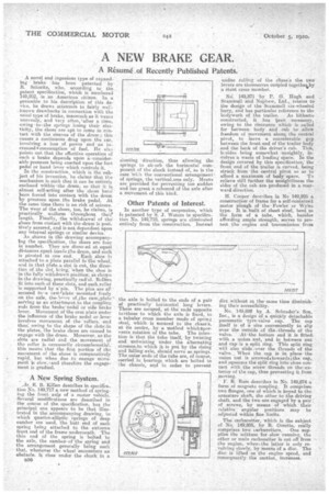
sir. E. B. Killen describes in specification No. 149,717 a new method of springing the front axis of a motor vehicle. Several modifications are described in the course of the specification, but the principal one appears to be that illustrated in the accompanying drawing, in, which quarter-elliptic springs of deep camber are used, the butt end of each spring being attached to the extreme front end of the frame underneath. The thin end of the spring is bolted to the axle, the camberscf the spring and the arrangement generally being such that, whenever the wheel encounters an obstacle, it rises under the shock in a
338
slanting direction, thus allowing the springs to alyorb the horizontal component of the shock instead of, as is the case with the conventional arrangementof springs, the verticaLone only. Means are provided for preventing too sudden and too great a rebound of the axle after a movement of this kind.
Other Patents of Interest.
In another type of suspension, which is patented by S. J. Waters in specification No. 149,718, springs are eliminated entirely from the construction. Instead
the axle is bolted to the ends of a pair of practically horizontal long levers. These are secured, at the ends opposite toithose to which the axle is fixed, to a tubular cross member made of spring steel, which is secured to the chassis, at its centre, by a method whichaprevents rotation of the tube. The intention is that the tube itself, by twisting and untwisting under the alternating stresses.to which it, is put by the rising and falling axle, should serve eh. springs. The outer ends of the tube are, of course, carried in bearings which are bolted to the chassis, and in order to prevent undue rolling of the chass:s the two levers are theniseives col-listed togethei,by a Stout cross member.
NO. 149,871 -by P. G. Hugh and Scammell and Nephew, Ltd., relates to the design of the &oilmen six-wheeled lorry, and has particular reference to the
bodywork of the trailer. As hitherto constructed, it has loen necessary, owing to the clearance which is called for between body and cab to allow freedom of movement about the central pivot, to leave a considerable gap between the front end of the trailer body and the hack of the driver's cab. This, liK-sides being somewhat unsightly, involves a waste of loading space. In the design covered by this specification; the front end of the trailer is enrved, being struck from the central pivot so as to afford a maximum of body space. To relieve still further the unsightliness the sides of the cab are produced in a rearward direction.
H. Cooper describes in No 149.905 a construction of frame for a self-contained motor plough of the Fowler or Wyles type. It is built of sheet steel, bent to the form of EL tube, which, besides affording ample strength, serves to protect the engine and transmission from
dirt without at the same time diminishing their accessibility.
No. 149,898 by, A. Schrader's Son, Inc., is a design of a quickly detachable pneumatic 'tyre-valve cap. The cap itself is of a size conveniently to slip over the outside .of the. threads of the
Valve. At' the bottom -,end it is fitted, with a union nut, and in between nut and cap-is a. split ring. This split ring will also slide overthe threads of the valve. _ When the cap is in place the union nut is screweditowardscthe cap, and squeezesthe split ring into close contact with the screw threads on the .exterior of the cap, thus preventing it from moving.
F. R. Ram describes in No. 149,874 a form of magneto coupling. It comprises two flanges, one of which is keyed to the armature shaft, the other to the driving shaft, and the two are engaged by a pair of screws, by means of which their relative angular positions may be adjusted within fine limits.
The carburetter, svhish is the subject of No. 149,805, by R. Coeette, realty
comprises two carburetters. One supplies the mixture for slow running, the other or main carburetter is cut off from the engine, when k the latter is only revolving-slowly, by means of a disc. The disc is lifted as the engine speed, and consequently the suction, increases.