


Patents Completed.
Page 22
If you've noticed an error in this article please click here to report it so we can fix it.
Complete specifications of the following patents will be sent to any address in the United Kingdom upon receipt of eightpence per copy at the Sale Branch, Patent Office, Holborn, W.C.
CLUTCH.—Broadbent. No. 29,520, dated 20th December, 1910.—This invention relates to friction clutches of the typo in which the two main elements consist of a flanged disc and segmental plates, which are forced into contact with the inner surface of the flange hy various mechanical means. A second flanged disc is arranged on the second shaft and carries radially-movable wedge blocks, which engage the inner surface of the outer flange, and are mounted in holes in the inner disc. A number of segmental blocks are arranged between the flanges of the two flange discs, and a sliclable sleeve is mounted on the boss of the second disc. This sleeve carries adjustable wedges, which are adapted to engage links pivoted to the radially-movable wedge blocks and force them into engagement. The operation is carried on against the influence of springs which, when declutching, assist the blocks to become disengaged.
INTERNAL-COMBUSTION TUEIIINE.—Lewthwaite. No. 20,994/10. Cognate Application No. 29,086/10, dated 5th September, 1910.—This specification describes a gas turbine in which a rotor disc or discs are provided with impact pockets round the edge and the explaled charge is allowed to enter these pockets from chambers fixed in the side of the casing. These impact pockets we curved alternately in opposite
directions, so that the machine is reversible. The outlet ports are provided in the easing between the inlet ports, there being two of these, one for each direction of rotation. The mixture is compressed in a separate cylinder and exploded in a chamber opposite the in let port. The direction of its entry to the rotor chambers is controlled by means of reversing plugs situated in the chamber. Further details and alternative arrangements are described and illustrated in the .specification.
PETROL V ALVE.—Abingdon-Eeco, Ltd., and Another.—No. 25,341, dated 1st November, 1910.—This invention relates to a petrel-valve device for controlling the delivery of spirit from a tank. It is found in practice that ordinary taps are objectionable for several reasons, and in this specificatien there is described a valve device comprising a vertical tube passing through the tank and fitting into a suitable outlet bush at the 'bottom; the
device is provided with a conical valve to close the outlet. This valve is formed on a spindle passing upwards through the tube and secured to a cap nut that is screwed on to the tipper end of the surrounding tube. By screwing this cap nut up or down, the valve is closed or opened as required. If desired, a spring control may be provided, or a bayonet-joint device may he used for holding the valve in its open position.
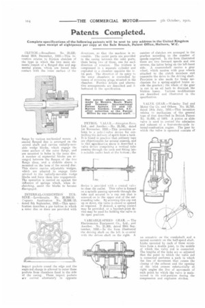
VARIABLE.SPEED GEAR. — The Electromotor Equipment Co., Ltd., and Another. No. 21,806, dated 20th September, 1910.—In the form illustrated the driving shaft on the left is co-axial with the driven shaft On the right. A number of clutches are arranged in the gearbox according to the number of speeds required. In the form illustrated there are two forward speeds and one reverse, the latter being on the left-hand side. A countershaft carries a gear wheel, which meshes with gear wheels attached to the clutch members and transmits the drive to the driving shaft. Provision is also made for brake mechanism for a spring-applied brake inside the gearbox ; the whole of the gear is run in an oil bath to diminish the friction losses. Various modifications are described and illustrated in the specification.
VALVE GEAR.—WoLselev Tool and Motor Car Co. and Others. -No. 16,783, dated 14th July, 1910.—This invention relates to mechanism of the general type of that described in British Patent Nu. 16,420, of 1909. A piston or slide valve is used to control the admission and exhaust of a four-stroke-cycle in. ternal-combustion engine. The gear by which the valve is operated consists of an eccentric on the crankshaft and a second eccentric on the half-speed shaft. Links operated by each of these eccentrics form a double joint, to the middle of which the valve rod is connected. The lengths of the links are so adjusted that the point to which the valve rod is connected performs a path in which the line of movement that causes the closing of the exhaust and the opening of the inlet crosses substantially at right angles the line of movement of such point by which the valve is maintained in its mid-position during the compression and explosion strokes.