


Fuel Injected with Compressed Air
Page 84
If you've noticed an error in this article please click here to report it so we can fix it.
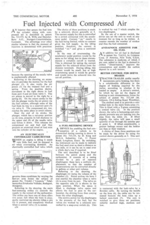
AN injector that sprays the fuel into the cylinder. along with compressed air is described in patent No. 715,575, by R. Wille and DaimlerBenz A.G., Stuttgart-Untertiirkheim, Germany. The advantage over other similar schemes is that the moment of injection is determined with precision
because the opening of the nozzle valve is mechanically effected.
Referring to the drawing, an eccentric (1) provides the motion for the fuel plunger (2). It also works the air piston (3) via the trapped fuel and a spring. From the position shown, movement to the right draws in fuel from port 4 and air from valve 5. The air piston is moved to the right. by a spring (6). On the return stroke to the left the plunger works the air piston via the fuel column, although some of the fuel finds its way to a reservoir port (7) via valve 8. The compressed air, too, reaches the same place to await release.
Near the end of its stroke, the plunger, which has a cut-away portion on its nose, presents its full diarheter to the upper end (9) of the needle valve and forces it down. This releases the compressed air and fuel and thus projects an atomized cloud of fuel mist into the cylinder of the engine.
AN ELECTRICALLY CONTROLLED CARBURETTER W/HEN an engine is idling it needs VI' very little fuel, and its demand is nil when overrunning downhill. An electrically controlled fuel valve which governs these conditions by varying the fuel-jet area forms the subject of patent No. 714,662 (" Licencia " Talalrnanyokat Frtekesito Vallalat, Budapest, Hungary), Referring to, the drawing, the main fuel-metering orifice (1) controls the supply to the venturi of the carburetter. The orifice can have one -of three effee. tive areas: full when the bore is clear, partly restricted (as shown) when a pin (2) is present, and completely blocked when a conical valve (3) is.seated.
n34 The choice of these positions is made by a solenoid, shown generally at 4. The current supply for this is controlled by a switch connected with the accelerator pedal. Current " on " results in the fuel being limited, whilst no current gives the full supply. In the idling position, therefore, the current is switched " on " and gives a restricted supply.
In the case of overrunning, the accelerator pedal position would be the same as for idling, but-in these circumstances a complete cut-off is wanted. This is obtained by taking the current supply for the solenoid direct from the dynamo terminals. During idling, this current would be small, but at high overrunning speed it would be greater and would move the solenoid into the cut-off position.
A FUEL-METERING DEVICE
A DEVICE for enabling the fuel conZ-3. sumption of a vehicle to be determined during running is shown in patent No. 715,135, by D. King and M.G.A. Industries, Ltd., 11 Forest Road, Loughton, Essex. By switching, the instrument can be made to indicate the fuel used over as short a distance as one mile, or it can be set to read over a whole day's run if required.
The unit described is to be fitted between the petrol pump and the carburetter. It consists of a casing divided by a pair of opposed diaphragms; these have a uniform displacement so that the number of reciprocations can be converted directly to gallons or other unit volume.
Referring to the drawing, the diaphragm (1) varies the volume of the chamber (2). Petrol arrives via bore 3 and reaches the chamber when a valve (4) is away from its seat. The valve on the opposite side (5) is shown in the open position. When the space is filled, a discharge valve opens and allows the fuel to pass to the carburetter, the driving force then coming from the other diaphragm.
The motive power for the diaphragms is the pressure of the fuel, but the valves are worked by a solenoid controlled by a snap-over switch (6). This is worked by rod 7 which couples the two diaphragms.
By the use of a master switch, the driver can set the unit to work at any moment for as long as he wishes. A counter records the number of strokes and thus the fuel consumed.
ANTI-KNOCK ADDITIVE FOR OIL FUEL .
AN additive for oil fuel is disclosed in patent No. 714,213, by Celanese Corp. of America, New York, LLS.A., The substance is methylal, of which 3 per cent. added to the fuel is claimed to xeduce "Diesel-knock," improve the consumption and modify the carbon. deposit to a soft texture.
BETTER CONTROL FOR.SERVO BRAKES TRACTOR-TRAILER outfits usually I incorporate servo braking, but there is a considerable difference in the degree of braking required by the trailer, according to whether it be loaded or. empty. A driver's control, by which he can set the degree of braking to suit circumstances, forms the subject of patent No. 715,169 (M. Johnson, 134-6 Ealing Road, Wembley)..
The method used is to provide a controlled leak in the main brake-pipe (l). This is fitted with a T-piece containing a conical valve (2). In the position shown, the valve is bottoming and completely prevents any air leaking into the
pipe from the inlets (3). If lifted slightly, the valve will pass a small quantity of air through the annular gap
at point 4. If lifted -considerably, a greater leakage occurs and the brakes are then at their weakest A choice of these three positions can be made by the driver by using the control shown generally at 5. This unit is connected with the leak-valve by a Bowden cable. By turning the handle on the boss (6), the cable can be tensioned because the boss rides up a helical cam-track (7). The earn is notched to give three set positions, suitably marked high, medium and low.