


A NEW CARBURETTER.
Page 32
If you've noticed an error in this article please click here to report it so we can fix it.
A Resume of Recently Published Patent Specifications.
TNVENTIONS relating to carburet_Lters have not for some time been conspicuous for originality, the differences from ordinary practice have been rather of the nature of the difference between Tweedledum and Tweedledee.
It is quite refreshing to see something which, to an extent, breaks away from the groove to which carburetter design has lately been confined. The specification of E. Jennings, No. 231,275, describes a carburetter without a jet ; a ring of porous material being used as a means of vaporizing the petrol. An outer chamber is formed of metal and has an inner lining which is made of some porous material. The petrol is introduced into the space between the metal and the porous material.
A central pin forks a guide for a hollow plunger which carries with it a diaphragm. An eccentric at the top and a spring at the bottom control the movemeat of the plunger and diaphragm. As shown, a hood is fitted which leads to the supply pipe of the engine. Air, when drawn in below the diaphragm, comes into contact with the walls of the porous material, and draws with it gas from, the evaporation of the petrol, Extra air enters from above the diaphragm, and by the regulation of the eccentric the desired mixture is obtained, the movement of the diaphragm restricting one way and enlarging the other. • The inventor claims that by this arrangement it is not necessary to have a throttle, but he does not make this point very clear. The use of porous material for this purpose is not new to us.
A Servo Brake Which Acts in Both Directions.
MITCH attention has recently been given to the design of servo brakes, especially those which are intended to he operated by the movement of the car in either a forward or backward direction.
The latest 'invention in this direction. is that of Frederick Royce, No. 231,312. The accompanying sectional view shows a shaft (A) which is driven at a reduced speed from the propeller shaft. At the end of this shaft is a pinion which meshes with an internally toothed ring (B) and with a gear (C). It will C-49 he seen that by this means B and C are always revolving in opposite directions.
The boss of B is provided With a dog engagement, the teeth of which are formed like a saw, so that they can drive only in one direction. The boss of the
gearwheel (C) is provided with a similar dog engagement, but with the teeth slanting in the opposite direction.
. By means of this arrangement, no matter in which direction A may revolve, it aways imparts to the shaft which carries B and 0 a rotary motion
• in one direction. A continuation of this shaft carries a plate clutch, -one member of which is continually revolving. The lever (F) is free to revolve on its shaft, and is connected by means of a rod to the brake pedal, and is the means whereby the servo brake is brought into .action. One end of the -boss of this lever is .provided with a ball thrust bearing and adjusting nut, whilst the other end of the boss has teeth cut in it with slanting surfaces on one side. These teeth engage similar teeth at G, so that a slight rotary movement of thelever causes a compression to take place between the outer members of the clntch, which sets up friction with the always running member of the clutch, and so cases the servo effect. The rod which actually applieS the brake is connected to the stud (H).
An Improved Tipping Body.
A PRACTICAL form of tipping body is shown in specification No. 231,282. P. Murdoch and J. Heron, of Belfast. Channels are fitted alongthe sides of
the chassis to receive rollers mounted on brackets attached to the body. These rollers engage the channels.
The body can be brought to a tipping position by hand gear or power, as considered desirable. The specification claims that by the introduction of a turntable, as shown, the body can tip on either side as well as at the rear. By the use of a body of this type, in which the centre of gravity is not raised, but merely shifted towards the rear, there is considerable saving of effort.
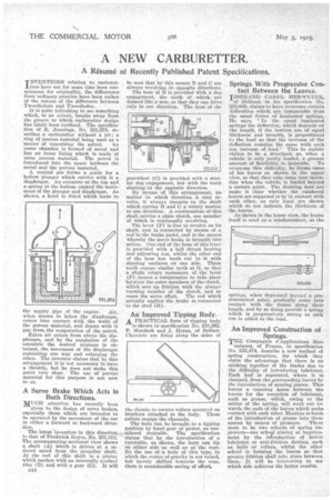
Springs With Progressive Con. . tact Between the Leaves.
IJSBRANP CAREL HERWEYER,
of Holland, in his specification No. 230,000, claims to have overcome certain difficulties which are inseparable from the usual forms of laminated springs., He says, "In the usual laminated springs the deflection, which depends on' the length, if the lamina are of equal thickness and breadth, is proportional ts the load so that the increase of the deflection remains the same with each ton increase of load." This he rightly claims to be a drawback as, when a vehicle is only partly loaded, a greater amountof flexibility is desirable. To overcome this difficulty, he forms some of his leaves as shown in the upper view, so that they -only conic into operation when the vehicle is loaded beyond a certain point. The drawing does nos make it clear 'whether the cambered leaves are supposed to be in contact with each other, as only lines are shown which do not indicate the thickness of the leaves.
As shown in the lower view, the frame itself is used as a reinforcement, as the springs, when depressed beyond a predetermined point, gradually come into contact with the frame along their length, and by so doing provide a spring which is progressively strong as each ton is added to the load.
•
An Improved Construction of . Springs..
THE Compagnie d'Applications Mee
aniques, of France, in specification No'. 222,474, describe a new method of spring construction, for which they claim the advantage that there is no sticking together of the blades due to the difficulty of introducing lubricant. Each leaf is separated, where it is clamped, from the purrounding leaves bythe introduction of spacing pieces. This leaves a tapering space between the leaves for the reception of lubricant, such as grease, which, owing to the action of the spring, will work out towards the ends of the leaves which make contact with each other. Mention is Made of the introduction of grease into these spaces by means of pressure. There seem to be two schools of spring irri. provers—one school aiming at improvement by the introduction of better lubricant or anti-friction devices, such as balls or rollers, whilst the .other school is forming the leaves so that greater friction shall take place between them. It will be -interesting to see which side achieves the better results.