


A Re'sume of Recently Published Patent Specifications
Page 52
If you've noticed an error in this article please click here to report it so we can fix it.
Separate Block for Engine Valves
TO facilitate valve maintenance in a side-valve engine is the aim of a scheme proposed in patent No. 593,942, which comes from B. Westwood, 51, Enville Road, Kinver, Staffs. It is suggested that the valves be housed in a separate casting which can be detached as a whole.
A section across a multi-cylindered • block is shown in the drawing, in which is the proposed valve block. It is screwed to the. side of the cylinder block, a thin gasket being interposed, and long studs (2) are provided to carry the inlet and exhaust manifolds in the usual way The cylinder head extends over the valve block, and is bolted to the assembly. Cooling-water passages are provided in the block; the water is conducted through special pipes attached one to each end. The advantage of the scheme is that the valve assembly can be detached and taken to the bench when work has to be done, instead of the mechanic' having to reach into some awkward place across the wings of the vehicle, • ROTARY ENGINE DESIGN
AN engine having no reciprocating parts has been the aim of numerous inventors, and patent No. 594,113 shows suggestions in this field. The inventor is I Nezeloff, Drancy, France.
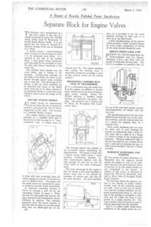
This engine employs the gear-pump principle in a modified form and is illustrated in the drawing as a " fourcylindered " unit. A master rotor (1)
is fitted with four projecting lobes (2), which engage in recesses (3) bored in a pair of smaller rotors. The master and the small rotors are connected by -gears to maintain correctly timed relationship.
In operation incoming mixture is drawn in through a port (4) by the expanding volume of space 5. When the lobe (6) approaches .the bottom, the space decreases and Compression occurs, followed by ignition. The resulting expansion gives the power impulse to the lobe and the gases are carried round until they are discharged out of the A38 • exhaust port (7). The patent mentions that sealing the working faces is materially assisted by providing a series of fine grooves across all the sealing surfaces.
PROMOTING UNIFORM RUNNING IN TWO-STROKES
IT is a well-known fact that small two1 stroke engines are difficult to throttle down without incurring four-stroking or other erratic running. Patent No. 593,663 discloses a modified design claimed to regularize two-stroke running. The patentees are J. Hutton and W. Davis, 28, Broughton Hill, Letchworth, Herts.
The drawing depicts the cylinder of an air-cooled engine embodying the improvements. The piston is made with a hollow crown which forms a small auxiliary combustion chamber ( 1 ). This communicates directly with the inlet passage (2) and has an exit (3) which leads to the main combustion space.
The main advantage of the engine is that thecharge in the small chamber is always clean, and is not diluted by remnants of exhaust gas, like that of the main chamber, An extra sparking plug (4) is provided to fire the small chamber through its inlet port as it lines tip at top dead centre.
A dual charging pump, of the pattern which provides a small constant charge on every stroke, irrespective of setting of the main throttle should be used DRIVEN FRONT-AXLE UNIT
PA'TENT No. 594,320 comes from the Timken-Detroit Axle -Co., Detroit, Michigan, U.S.A., and deals with the design of front-axle driving hubs. The aim is to produce an assembly that, by
the use of the same hub outline, permits interchangeability of. wheels with the rear axle.
The specification asserts that the chief difficulty has been the size of the steering trunnions, and the improvement lies in a means for keeping these on a reduced scale.
Plain, small, hardened pins are used. the inner end of each forming . the journal, in conjunction with a bush (1). The outer end is_a tight fit in a flange (2), which is bolted to the swinging hub assembly. The fit is sufficiently tight to obviate the need tor any locking device and is achieved by freezing the pins in solid carbon-dioxide (" dry ice ") before assembly.
RESILIENT SUSPENSION FOR ENGINES
IN any system of engine mounting it is desirable that the 'supports should permit the engine to rock on its principal axis (the one containing the centre of gravity), as by this means shocks are not transmitted to the chassis. A scheme of this nature is disclosed in patent No. 593,121 by Mctalastik, Ltd., and A. Hirst, both of Evington Valley Road, Leicester.
The drawing shows the general outline of the scheme, in which rubberbonded units of the sandwich pattern are used. Line 1 is the axis of oscillation, and the resilient members are disposed symmetrically about it. On each side of the gearbox is mounted a sand' wich unit (2), whilst the front is supported on a single member (3). The front member may be located at point:4 without departing from the principle.
Unit 5 is a rubber buffer which limits oscillation of the engine about its axis.