


Germany s Premier Tool Works.
Page 19
Page 20
If you've noticed an error in this article please click here to report it so we can fix it.
A Visit to the Berlin Works of Ludwig Loewe 81 Company, Limited.
A represedtative of '` TEE COMMERCIAL MOTOR '7 recently v.sited the immense works of Ludwig Loewe and Co., Ltd., at Barlin, and was greatly impressed by the perfe.:t order and cleanliness which prevailed in every department of that well-known tool factory. To attempt to give a complete description of this factory, with its fine power house and generating plant, its lofty machine and fitting shops, its powerful overhead, electric cranes, and the clean, and well-fitted lavatories, in the latter of which each workman has his own locker, wherein to keep his overalls, towel, and other private property, would require far more space than can be spared within these pages, We must, therefore, confine our remarks to such of the company's recent introductions as are of especial interest to the motor manufacturer.
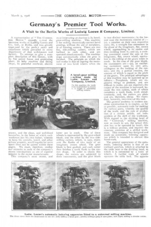
This company's most recent, and
most interesting production is its bevelgear-milling machine. This machine is for milling theoretically-correct bevel gearing, without the aid of templates, or of forming cutters_ There are two flat, side-milling cutters, which are inclined to each other, and are operated simultaneously. The machine stops automatically when the gear is finished. The principle on which the tool works is that of copying the movement of two bevel wheels when the
latter are in mesh. One of these
wheels is represented by the gear-wheel blank, and the other by the two sidemilling cutters, which, in turn, represent the flanks of two teeth of an imaginary crown wheel. The gear blank is first gashed, and each cutter then finishes a tooth flank to the cor rect shape. In order to obtain this shape, the cutters are subjected to three movements, and the gear blank to two distinct movements ; in the former case the movements consist of :(a), a rotation on their own respective axes; (b), a straight line movement in the plane of the imaginary, flat, crown wheel, approaching to its centre and then receding from it ; and (c), a rocking movement tound the axis of the imaginary, flat, crown wheel, equivalent to the rolling of the gears when in mesh. In the case of the gear blank, the movements are :—(a), an oscillating, movement upon its own axis, analogous to the rocking of the cutters; and (b), a partial rotation, the amount of which is equal to the pitch of the gears. The principal advantages of this machine may be summed up as follows :—Templates; which are expensive things to produce, and are difficult to make, are not required; the output of the machine is increased, because the two cutters, each of which completes a tooth flank, work simultaneously, and, the cutters are plain and are, therefore, cheap. We reproduce, herewith, two views of this tool. •
The general tendency in modern machine construction is to employ, as far as possible, automatic tools for making the various parts, whereby the quality of the work, and the rate of production of a certain article, are independent of the skill of the workman. With regard to the dividing head of the " Universal," milling machine, now so much in use, the actual division has to be operated by hand; this is a tedious process, and requires the constant attention of a skilled work.. man. This company has designed and made an automatic, indexing apparatus which is intended to obviate this hand-work.
The general appearance of the automatic, indexing device is that of an enclosed gearbox, which is attached to the table next to the dividing head, to which it is connected by a train of wheels. A further train of wheels operates the table feed. The appara
tus can only he used on a milling machine which is provided with a dividing head and change-gear wheels, and it is intended for work that does not require to turn on its own axis while the cutter is in operation. The spindle
of the dividing head can be tilted to any angle, and the apparatus may be used for a large variety of such work, such as bevel wheel stocking, milling straight-toothed wheels, or for the making of milling cutters. The three illustrations at the foot of page 587 show the machine.
The automatic feed of the table, with its quick-return motion, is brought about by means of the change wheels already mentioned, and these connect the indexing apparatus with the table feed, and the ratio of these change wheels determines the amount of tool, or table feed per revolution of the work on its own axis.
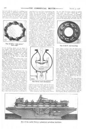
With the growing demand for increased accuracy in the machining of many of the finer details of a motor vehicle, the grinding machine is daily cooling into more general use, and a fair amount of attention has been given to its perfection recently, by many of the well-known makers, amongst ‘vhom is the Norton Company of America. Ludw. Loewe and Company is the European agent for this class of tool and the accompanying illustration of a cylindrical-grinding machine shows one example of a type that has undergone more improvement, perhaps, than any other form of grinder, with the re sult that it is now fast supplanting the lathe for the finishing of cylindrical work, irrespective of the material of which the piece is being made. The practice of rough turning on a rapidreduction lathe, and then finishing on a cylindrical grinder is not only the most accurate, but also the most rapid method of reducing work to the exact diameter that is required. Ludw. Loewe's little booklet on the subjelA of grinding is well worth perusing, cs it brings out many points which have not previously been deal:with. The Globe tool sharpener, which is another (If the American tools that are handled by this company, is a particularly handy grinder for the tool-room, or for the general shop. It is a grindeenclosed in a hollow sphere, and is sespended over a large body of water; it combines the advantages of a wet grinder with none of the objectinnable features of the latter. The housing and the wheel can be swivelled, separately or together, through 360 degrees, in
order to suit the work, and for the purpose of admitting the light to any part of the work. The double-ended spindle is fitted with a bevelled, cup-shaped wheel, and one of the plain variety. This company has long been known for the ball bearings which it makes and sells as the " D.W.M.," or " D.W.F." ball bearings. As formerly made by the company, these bearings were fitted with spiral springs for the purpose of separating the balls, but, in time, these springs lost all their temper, and they then became pressed up solid, and were of no further use for the purpose of separating the steel balls. The bearing as now made, however, is of quite a different form. The same high-class quality of carbon steel is employed for the ball races, but the balls are contained in a "one-piece " rnetal cage, as shown by the illustration in the first column on this page_ The effect of making the cage in one piece obviates all the troubles which are usually associated with cages that are made in two halves, and which are held together by means of screws, rivets, or clips. When well lubricated, and running with their full load, these bearings have a co-efficient of friction of only 0.0012. The appearance of the complete bearing is shown by the accompanying illustration.
One very important fact was driven home to our representative during his visit to this company's works in Berlin, and that was, that English tool steel is still considered among the best that the world can produce, and in this large Berlin factory, Thos. Firth and Sons' "
Nova" tool steel was used throughout. Ludw. Loewe and Company's London offices and showrooms are at Farringdon Road, Clerkenwell, E. C.