


A NOVEL FORM OF SELF-ENERGIZING BRAKE.
Page 74
If you've noticed an error in this article please click here to report it so we can fix it.
A Resume of Recently Published Patent Specifications.
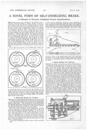
THE brake shown in the specification No. 280,163 of Raymond Alexandre Babel, of Clichy, France, contains a novel feature in the fact that the expanding corn is provided with a sliding piece which can, by sliding through a slot in the head of the shaft, accommodate itself to the various positions taken up by the shoes when acting in a forward or a backward direction. Fig. 1 shows the brake in the "off " position, where it will be seen that the upper ends of the shoes impinge upon the circular portion of the expander shaft head. While in this position, the spring shown pulls the lower part of the brake shoes to one side, thus centring them by drawing the oval hole to one side so that it comes in contact with the fulcrum pin. Fig. 2 shows the brake in operation, or rather commencing its operation, as, if the drum should revolve in the dir6ction of the arrow, the pressure of the right-hand shoe on the drum would move the shoes into the position shown in Fig. 3, where it will be seen that the oval hole has changed its position and thus enabled the left-hand shoe to be brought into contact with the drum,
Fig. 4 shows the function of the sliding piece which acts to expand the shoes, as, in this case, the direction of the drum is shown by the arrow and it will be seen that the sliding piece has moved in its slot, thus allowing the upper ends of the shoes to take up a position which, whilst balancing their pressure evenly on the drum, allows the self-energizing effect to take place.
A Multi-pull Brake for Trailers.
WE have on many occasions advocated the use of some kind
of brake in which the driver can take more than one pull, because with heavy vehicles, one pull can never satisfactorily apply a trailer brake. The device shown in the specification No. 289,184, of Leonard George Ward, has been mentioned in this journal before, but an addition to the already described arrangement is the subject of the present patent.
The novel feature consists of an arrangement whereby both, the backward and the forward movement of the hand lever have the effect of applying the brake. It will be seen that a long, ratcheted bar has a cable attached to its rear end ; this cable passes to the brake of the trailer, so that when the ratcheted bar is moved forward the brake is applied. The hand lever is mounted on a fulcrum and has two pawls, one urging the bar forward as the lever is pulled back, whilst the other pawl urges the bar forward as -the lever, is pushed forward.
As the bar is advanced, tooth by tooth, a detent prevents B48 the main object of the double-acting lever is to make the application of the trailer brake a quicker operation, as there is always a considerable amount of slack to be taken up in the cable.
A Clutch Behind the Gearbox.
THERE is nothing very novel in the idea of introducing a clutch behind the gearbox so that all drive from the rear axle shall be interrupted while a change of gear is being made. This idea is older than the present movement for -introducing a free-wheel in this position. The novel feature of the patent No. 289,494, of Colin B. Wilson, of Tientsin, China, appears to lie in the. coupling of such a clutch to the change-gear mechanism so that, whenever the gears are in neutral, the clutch behind the gearbox becomes disengageh.
The clutch shown is of the positive-dog type and is slid in and out of engagement by means of a connecting link and a cam on the selector shaft, so that whenever a neutral position is reached the dogs are disengaged. It is true that such an arrangement will* prevent damage to the gears through unskilful handling, but the difficulty that has been experienced in earlier efforts in this direction has been that it was found just as difficult to judge the speeds of the halves of the dog clutch as it is to judge the peripheral speeds of two gears that are to be engaged. It would be more useful if inventors would turn their attention to some form of friction clutch that would function well in such a position so that there would be no need to judge speeds at all. 1"he difficulty is that no friction clutch has, as yet, been made that will transmit the torque of the low gears and yet not be inconveniently large.