


HINTS ON MAINTENANCE.
Page 72
If you've noticed an error in this article please click here to report it so we can fix it.
An Improvement to the Clutch-shaft Joint of a Daimler. Dynamo Removal on the Model 417 Associated Daimler. A Peerless Big-end Modification. •
Increasing the Life of the Clutch-shaft Joint on a B-type Daimler.
A FAULT sometimes found on the B-type Daimler _LA chassis is that the front coupling of the clutchshaft, which is of the flexible-fabric pattern, has a very short life, this applying to almost every coupling of the flexible pattern which has been tried in this position. One of our readers, in order to increase the life of this item, made an alteration which appears to be quite satisfactory, as it has been in use for over a year without any trouble. In addition, it is claimed that the
alteration has simplified gear changing to a remarkable degree.
The clutch is of the cone type with fabric facing. It is not withdrawn direct by means of a pedal gear acting on a sleeve secured to the cone, as is usually the case, but is pulled via the coupling and, as the spring is rather strong and the clutch sometimes apt to stick for a time, the coupling is subjected to an abnormal end pull. We will now describe how our contributor prevented this stress.
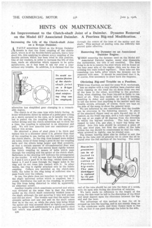
He obtained a piece of steel plate t in. thick and turned this to a diameter about in. greater than that of the coupling in use, boring out the centre to fit over the clutch sleeve. In the ring thus formed were drilled six holes, three of these being a good fit for the coupling bolts and the others being larger and filed eccentric, so that a certain amount of circumferential float was permitted. This plate was merely fixed rigidly behind the fabric coupling by means of bolts which pass through the coupling and the spider of the clutch shaft. Reference to the drawing will indicate the arrangement to the reader. It will be seen that the bolts numbered 1, 2 and 3 are a good fit in the ring ; whilst those numbered 4, 5 and 6 pass through the bigger holes in the ring and do not come into contact with it. In other words, the ring is rigidly attached only to the fabric coupling. Collars are provided on the clutch-cone bolts, the holes in the ring being of sufficient size to pass freely over the collars.
In use, the plate does not interfere in any way with the slight universal action which is required, but it evenly distributes the pull on the coupling, so preventing this from being distorted to what is, apparently, an abnormal extent.
Another trouble which sometimes occurred and which was obviated at the same time is that the driving spider on the clutch shaft constantly worked loose on the shaft, although the nut securing it was well pinned and did not move. The trouble was that the spider has straight splines and any end pull on the shaft comes first on to the nut, so while the plate was being fitted the spider nut was serewed down as tightly as possible and the spider held additionally by a good-quality steel bolt which was passed through a 11-in. hole drilled
B46 through the centre of the boss of the spider and the shaft. This Method of dealing with the difficulty has proved quite effective.
Removing the Dynamo on an Associated Daimler Engine.
WHEN removing the dynamo used on the Model 417 Associated Daimler engine, many also dismantle the carburetter, but this is not essential. The first thing to do is to remove the stud which will be found at the rear near side of the engine (this can be done by utilizing two nuts locked together). Then take out the remaining two bolts, after which the dynamo can be removed with ease. It should be mentioned that it is, of course, first necessary to draw back the magneto.
Obviating Big-end Trouble on a Peerless.
THE 5-ton Peerless, as used for some W.D. workshops,
has an engine with a very shallow base chamber and when running on the road the oil flows from one end of. the base to the other, according to the gradient. Thus, when climbing, the front big-end is liable to run short of oil. This may easily lead to a dry bearing, resulting in delay and expense, as there is nothing to tell the driver that anything is the matter until the trouble occurs, although, of course, there are taps at the side of the sump to show the general leveL We are informed by one contributor that the trouble can be overcome in the following manner. In place of the standard dipper used on each big-end cap or, if desired, on the front cap only, drill a hole right through the cap at an angle of 45 degrees from the direction in which the big-end revolves. The hole -must be tapped to take +-in. gas pipe, a taper tap being employed. Into this hole should be screwed a piece of gas steel pipe, but first the orifice of the hole within the cap should be countersunk so that the tube; when screwed in tightly, can be riveted over.
The bronze bearing must also be drilled to suit the hole in the tube and oil grooves cut to allow the oil to travel over the full surface of the bearing. The outer end of the tube should be cut into the form of a scoop, with its open side facing the direction of rotation.
We have made no reference to the length of the scoop, for this must be left to the discretion of the fitter and must depend upon the clearance between the bigend and the base.
The advantage of this method is that the oil is scraped up into the bearing, and is not merely flung on to the crankcase walls, and from thence back to the rods, so that it can pass through the holes in the side.