


AN ENTIRELY NEW
Page 12
Page 13
Page 14
Page 15
If you've noticed an error in this article please click here to report it so we can fix it.
>H STEAM WAGON.
The Brotherhood, with Boiler Located Acr H.P. Cylinder at Off Side, L.P. Cylinall Front. Undertype Engine Two Speeds : Side : Independent Bevel Drive to Each
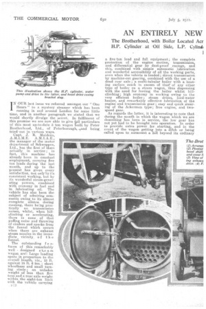
IN OUR last issue we referred amongst our "One Hears" to a mystery steamer which has been running in and around London for some little time, and in another paragraph we stated that we would shortly divulge the secret. In fulfilment of this promise we are now able to give 4111 particulars of this most un-to-date 5 ton wagon built by Peter Brotherhood, Ltd., of Peterborough, ,iand being tried-out in various ways. Capt. J. R. Maidens,
A. M.I.M.E. A.M. I. A. E. , the manager of the motor department of Schweppes, Ltd., has the first of them actually in service ; in fact, this machine has already been in constant employment, carrying five ton loads during the last month, and up to the present has given every satisfaction, not only by its consistent working, but by its wonderful steam-gener ating powers, combined with economy in fuel and in lubricating oil. The vehicle has also been the subject of admiring com ments owing to its almost complete silence during running, there being practically no transmission noises, whilst, when hillclimbing or accelerating, there is none of that puffing noise and throwing of cinders and sparks frorn the funnel which occurs when there are exhaust steam nozzles in the immediate vicinity, of the funnel.
The outstanding f e atures of this remarkably well designed s tie am wagon arc: Large loading space in proportion to the overall length, viz., 13 ft. against 18 ft. 6 ins. ; short wheelbase and small turning circle ; an unladen weight of less than five tons and a rear axle weight within the eight-ton limit with the vehicle carrying . 1213
a five ton load and full equipment; the complete protection of the engine motion, transmission, and differential gear by dust-proof casings, and this, combined with simple automatic lubrication and wonderful accessibility of all the working parts, even when the vehicle is.loaded ; direct transmission by machine-cut gearing, combined with the use of a dead rear axle ; a multi-tubular boiler with a heating surface much in excess. of that' of any other type of boiler on a steam wagon, thus dispensing with the need for forcing the boiler whilst hillclimbing ; high economy in working owing to the very efficient boiler ; steam driers, feed-water heater, and remarkably effective lubrication of the engine and transmission gear ; easy and quick steering of the Ackerman type; free engine, and twospeed gear.
As regards the latter, it is interesting to note that during the month in which the wagon which we are describing has been in service, the low gear has not yet had to be brought into operation. In order to provide extra power for starting, and in the event of the wagon getting into a, ditch or being called upon to. surmount a hill beyond its ordinary power, -a device is provided by which H.P. steam can be admitted into the L.P. cylinder.
Having emphasized the chief points about this wagon, we will enter into a more detailed descri4p7 -Eon.
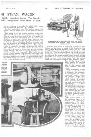
The boiler is of the totally enclosed return-tube type located across the front of the wagon. It consists of a central firebox with a set of 42 small fire tubes on each side slanting up into the combustion chamber at each end. Above these tubes at each side are six of much larger clilmeter leading to the srnokebox. The combustion chamber doors at each end are hinged. on the exhaust steam pipe brackets, the joints being packed with asbestos. The exhaust steam is conducted through the pivots and into a pipe -carried at the inner side . of each •door. Screwed on to each of these pipes are six exhaust steam nozzles, the size of which depends on the quality of the fuel employed. The boiler is not stayed in any manner, but is merely supported and hold to the frame. It is thus free to expand in any direction, and does not cause the disagreeable crackmg which often happens in rigidly stayed boilers when steam is being raised. Siemens mild steel is employed throughout the boiler, and the latter is tested to 300 lb. per sq. in., the normal working pressure being 200 lb. The total heating surface is 75 sq. ft., and the grate area 2i sq. ft. Tubular steam driers are fitted into the combustion chambers at each end, thus ensuring the provision of dry steam, slightly super-heated, to the cylinders. The boiler is carefully lagged, the lagging being covered with sheet steel. All the steam pipes are also carefully lagged with asbestos string. Two Crosby " pop" type safety valves are carried on the boiler, one at each side of the funnel, and these exhaust into the latter.
Many interesting points in boiler construction are to be noted. For instance, the water pipes can be disconnected under steam, the injector being provided with a push-button valve, which, if pressed down, prevents any blowing bank when the pipe is disconnected. On the other hand, the valve cannot allow the water pump to burst the pipes if it has been forgotten to lift it after connecting the pipes up again, as in this case, the water pressure merely lifts the valve automatically.
The engine, which is of the compound type, is of unusual a n d interesting .construction. The H.P. cylinder, which has a bore and stroke of 411 ins. and 8 i n s. respectively, i located longitudinally at the off side of the chassis, whilst the L.P. cylinder, which has a bore and stro—ke of 7 ins, and S ins. respectively, is positioned at the • other side. The two are connected together by a, bridge pipe, and the supply of steam from the super-heater is first carried to the H.P. cylinder and from thence to the L.P., ufter.which it
returns and passes through the combusion chamber nozzles.
The crosshead guides are circular. Thecrankshaft is located in a dustproof casing, and is positioned across the chassis,. It carries two flywheels, and the connecting rods work on a hardened steel pin bolted to each of the flywheels. The crankshaft
carries a very interesting form of eccentric gear, the eccentricity of which can be varied to control the engine as required and to effect reverse. One slide valve is operated direct from this eccentric, whilst the other is operated by a locking bar, also driven from the eccentric.
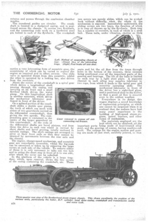
About the centre of the crankshaft is a spiral gear which drives a longitudinal shaft passing through the casing, and carrying at its front end a small flywheel which drives, the water pump. On this longitudinal shaft is another eccentric, which drives the mechanical lubricator positioned in front of the driver.
On a splined portion of the crankshaft slides a double spur pinion, the teeth of which can mesh with either of two gearwheels carried on the differential countershaft, thus giving the two speeds. The compensating gear is contained in the centre of the larger gearwheel on this countershaft. At the ends of the differential shafts are bevel pinions, and from these the drive to each rear wheel is carried by short shafts and bevel gearing, totally enclosed in suitable casings. The shaft casings are arranged to pivot at their front ends so that they cannot be strained by movements between the rear axle and the chassis.
The engine, change-speed mechanism, and eecentrio gear are remarkably accessible, whilst the big-ends can be examined or taken up by removing the large covers at each side of the vehicle. To remove either of these it is only necessary to take out one bolt and to swing the short stay in front of it to one side, after which the cover can be unbolted.
In the platform of the vehicle is a large trapdoor, which, upon removal, shows the two covers of the easing containing the crankshaft, etc. These two c,overs are merely slides, which can be pushed baok without difficulty, when the whole of the mechanism is exposed. Immediately underneath the sliding covers are two trays, the function of which is to trap oil thrown up by the flywheels. Each tray has a number of recesses, in each of which is a steel bidl. These balls, under vibration, chatter on their seats and let the oil flow from the trays through holes in the bottom of the recesses, these recesses being positioned over all the important parts of the gearing and bearings. The lift of the balls is limited on each tray by a light steel plate. A separate channel in each oiling tray supplies lubricant to two cups, from which it feeds to the Spiral gear and eccentric operating slide. The mechanical lubricator, in front of the driver has a sight-feed glass, and is positioned close to the boiler, so that a, good oil flow is ensured even in the coldest weather.
Everywhere in its design this wagon displays a sound knowledge of engineering principles, at which one cannot be surprised when it is realized that the makers have had many years' experience in the building of high-speed steam-engines, petrol tractors, and other forms of mechanism.
The materials employed are the best which can be obtained, all the important parts being made of heat-treated alloy steel, and the gearing, of course, having machine-cut teeth. The casings for the engine motion and gearing are made of cast steel, carefully jointed, so that
they will be absolutely oil-proof. Every pipe is provided with a tap at its lowest point, so that water may be drawn off in frosty weather, and the greatest care has been taken -to prevent the water of condensation deteriorating the lubricant. There is an exhaust steam separator and trap which drains condensed water from the exhaust steam before it enters the super-heaters within the smokeboxes.
The springing is of .quite an unusual type. For the front axle, one laminated spring is positioned in front of the axle and the other behind it. The weight of the front portion of the chassis, is carried on the centres: of these -springs,' whilst their ends bear on supporting bridges, each suspended by a single bolt at the ends of the front axle. • A light spiral spring between the bottom of the axle and the face of each bridge piece prevents rattling at these points. In addition the whole axle moves vertically between robust guides secured to the frame, and thus the stresses on the springs are confined to those due to the load.
The rear springing is almost exactly similar to that seen on railway wagons, the chassis being suspended by short bolts from each end. 'of each spring, and the springs being bolted at their centres to the dead axle, which latter is a solid, rectangular steel forging.
The wheels are of cast steel with hollow spokes, the hubs being bushed with phosphor-bronze. Twin solids of 1,050 mm. by 160 mm. are utilized on the rear wheels, and single solids, 900 am. by 140 mm., on the front wheels.
A very powerful screw brake operates,. by means
of a single shoe, on a ring bolted inside the rim of each rear wheel, These rings are of very large diameter; in fact, the maximum size possible, and thus the brake is very effectile. A simple. means of adjustment is provided by N' pin and a fork with several holes at each side. A powerful second brake is formed by the reversing gear.
The water tank, which is carried at the rear of the wagon, contains sufficient, water to run the vehicle a distance of from 26 to 30 miles, when the latter is fully loaded.
At the points where the lubrication of the chassis is not automatic-, a very neat and simple method of closing the lubricating holes has been devised. It ,consists in each case of a stout brass split-pin pushed into the hole, the spring of this pin being sufficient to hold it firmly in position, although it can be with'drawn quite easily when required.
Provision has been made for taking up wear ,throughout the chassis. Side play on the wheels can' be taken up to the 'extent of in. by adjusting the axle nuts. Similar provision is made on the bevel drive shafts, and if the wear becomes greater than this, special washers can easily be inserted.
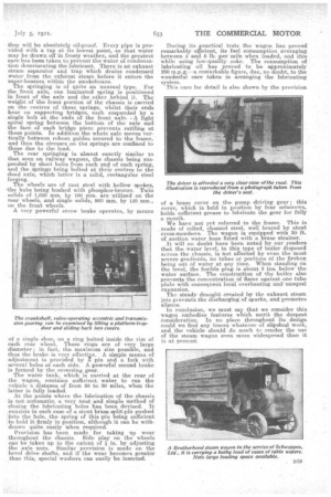
During. its practical tests the wagon has proved remarkably efficient, its fuel consumption averaging between 4 and 6 lb. per mile when loaded, and this while using low-quality coke. The consumption of lubricating oil has proved to be approximately 250 m.p.g.—a remarkable figure, due, no doubt, to the wonderful care taken in arranging the lubricating system.
This ca-re for detail is also shown by the provision of a brass cover on the. pump driving gear this cover, which iS held in position by four setscrews, holds sufficient grease to lubricate the gear for fully a month.
We have not yet referred to the frame. This is made of rolled, channel steel, well braced by stout cross-members, The wagon is equipped with 30 ft. of suction water hose fitted with a brass strainer.
It will no doubt have been noted by our readers that the water level, in this type of boiler disposed across the chassis, is not affected by even the most severe gradients, no tubes or portions of the firebox being out of water at any time. When standing on the level, the fusible plug is about 8 ins, below the water surface. The construction of the boiler also prevents the concentration of flame against one tube plate with consequent local overheating andunequal .expansi on. The steady draught created by the exhaust steam jets prevents the discharging of sparks, and promotes silence.
In conclusion, we must say that we consider this wagon embodies features which merit the deepest consideration. In no place throughout its design could we find any traces whatever of slipshod work, and the vehicle, should do much to .render the use of the steam wagon even more widespread than it is at present.