


Improving the Mechanics of the Crankshaft
Page 36
If you've noticed an error in this article please click here to report it so we can fix it.
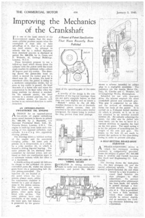
1T is one of the basic defects of the 1 conventional engine that the maximum cylinder pressure occurs when the crankehaft is least able to take advanTage of it, that is, at or about top dead centre. An attempt to remedy this by a radical departure from standard practice is disclosed in patent No. 565,276, by A. Green and F. Weinrch, 41, Garnage Buildings, London, W.C.Z.
These inventors propose to use a. folloWsup head which moves down the cylinder with the piston until the crank angle reaches its optimum value—about 35 degrees past top centre. The drawing shows the piston-like bead (1) which is moved via rocker gear by a timed cam (2). In action, the head is outermost when the piston is rising on a moderate compression stroke, but so soon as top centre is passed, the head
descends at a faster rate and raises the compression to its final value when the firing position (as shown) is reached. On the exhaust stroke, the head retreats to a normal position, but, on the suction stroke, it travels still farther in an outward direction to assist induction.
AN OPPOSED-PISTON • TWO-STROKE OIL ENGINE
ADESIGN for an opposed-piston two-stroke oil engine embodying many novel feat-tires is shown in patent
No. 565,150, by J. Reynolds, cin National Provincial Bank, Ltd., 61, Victoria Street, London, S.W.1. The engine is built-up from units each consisting of two opposed cylinders, each cylinder housing two _oppositely moving pistons.
The drawing shows a vertical section of the engine and its associated 'charging pump.. An inner pair of pistons (1) is reciprocated, as a whole, by a yoke member (2), in which is housed a Sliding big-end bearing. The outer pistons (3) are similarly interconnected by external yokes, and are timed so that one combustion space is at minimum volume while the other is at a maximum.
A double-acting air-pump (4) delivers its charge to the cylinders via pistoncontrolled ports (5), whilst the exhaust gases leave via a surrounding belt (6), also pistonscontrolled. The
injectors (7) are located at the point where the two pistons almost meet, whilst the cembustion chamber is formed by a pair of depressions in the piston crowns.
The cylinders are water jacketed about their midpoints, other parts being fitted with air-fins. The outer pistons have only two-thirds, of the stroke of the inner pair, but balance is preserved by the greater mass of the operating gear of the outer pair.
A novelty of the design is the construction of the big-end bearings; these are not quite complete halves, so that they can rock slightly and so create a " Michell action in the oil film. Another feature is the use of thermally insulated piston crowns; they are attached to the skirt with a mica washer interposed, the object being to protect the ring portion from heat damage.
PREVENTING BACKLASH IN TIMING GEARS DACKLAsii in timing mechanism Li leads to noise and inaccurateavalve operation, and patent No. 565,191
shows a. scheme intended to reduce play to a negligible minimam. The patentees are the Austin Motor Co., Ltd., II. Charles and C. Nossiter, all of Longbridge Works, Birmingham. _ Intended for use with spur-gear drive, the scheme employs the usual crankshaft pinion and camshaft gear. This gear is connected by an idler, and the method of Mounting this forms the basis of the patent It is carried on a T-shaped forked member (1) which is pivoted, at 2, on to an eye attached to an external screwed member (3). By suitably adjusting the latter, the idler can be pulled into close mesh, yet be free to move in a vertical direction to equalize the load on the two gears. The small spring 4 is for the purpose of cancelling-out the weight of the arm and gear. The bosses on the fork (1) are made to present flat surfaces to the close-fitting casing in order to prevent side-play.
A SELF-SETTING BRAKE-SHOE ADJUSTER
ABRAKE-ADJUSTING device in which the , necessary working clearance is compulsorily provided, forms the subject of paten No. 565,088 from S. Jenkins and Cardiff Junction Dry Dock and Engineering Co. Ltd,
Cardiff. • 'The drawing shows the back-plate (1), the shoe plungers (2) and the special .adjusting spindle. The lastnamed is quick-threaded (3) and when turned by a key it pushes a coned head between the shoe plungers to effect adjustment, To prevent unscrewing after adjustment has been made, the spindle is passed through a freewheel device shown genesally at 4. This is permitted to have a little backlash which thus enables the spindle to retreat slightly and so maintain the working clearance following any adjustment.