


The Reclamation of Worn Engine Valves
Page 21
If you've noticed an error in this article please click here to report it so we can fix it.
T"Eprocess of reclaiming engine valves by depositing suitable material on the previously prepared valve head, has been extensively employed during the past two or three years. The ravages of leaded petrol, and the difficulty of obtaining spares, have been responsible for the extensive development of the technique by which satisfactory results can be obtained.
In order ,to_ help those concerned in carrying out this work the Directorate of Vehicle Maintenance, M.O.W.T. has recently issued some essentially practical information on the subject.
In the matter of the depositing rod, this may be either Brightray or Stellite, The former is a nickel-chrome alloy obtainable in wire form, the price being 9$. 6d. per lb. for 7 lb. or over. Stellite, which is slightly harder than Brightray, is a chrome-cobalt-tungsten alloy, obtainable in rod form, The most usual size for the work under consideration is Ain. diameter, but it can also be obtained in rods of f-in. diameter.
It is most necessary to employ the correct grade of Stellite, and this must be Grade 6—marked red. The price of this grade is 21s. 3d, per lb. for A-in. diameter rode, and 32s. 6d. per lb. for the fin. diameter material.
Regarding the oxy-acetylene welding plant, acetylene from a low-pressure generator can be used, but high-pres sure acetylene is better. A 100-litre nozzle, or its equivalent, should be used in the welding torch. When employing high-pressure acetylene the gauge pressure of the acetylene should be 8 lb. and oxygen 10 lb. With generator acetylene the pressure of oxygen should also be 10 lb.
The use of a jig is almost a necessity when depositing the metal, and for continuous working it should be capable of being mechanically revolved at a maximum speed of 1 r.p.m. per minute. Control is carried out by the foot of the operative.
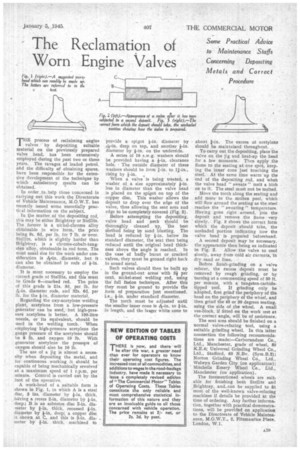
A work-head of a suitable form is shown in Fig. 1, in which A is a steel disc, 3 ins, diameter by f-in, thick, having a recess 2-in, diameter by fin. deep; B is an asbestos disc 2-in, diameter by fin, thick, recessed fin, diameter by fin, deep; a copper disc is shown. at C, and this is 2-in, diameter by 1-in, thick, machined to provide a spigot fin, diameter by Ys-in. deep on top, and another fin. diameter by f-in, on the underside.
A series of 16 s.w.g. washers should be provided having a fin, clearance hole. The outside diameter of these washers should be from 1-in. to 1j-in., rising by fin, , When a valve is being treated, a washer of a size approximately fin. less in diameter than the valve head is placed on the spigot on top of the copper disc. This washer allows the deposit to drop over the edge of the valve, thus allowing the seat area and edge to be completely covered (Fig. 2).
Before attempting the depositing, valve head and neck should be thoroughly cleaned up, the best Method being by sand blasting. The head is reduced by fin, below its standard diameter, the seat then being reduced until the original head thickness above the angle is reached. In the case of badly burnt or cracked valves, they must be ground right back to sound metal.
Such valves should then be built up in the ground-out areas with 31 per cent, nickel-steel welding rod, using the full fusion technique. After this they must be ground to provide the form of preparation just mentioned, i.e., Fin, under standard diameter.
The torch must be adjusted until the smaller inner cone is -k-in, to 1-in, in length, and the !Alger white cone to about fin. The excess of acetylene should be maintained throughout.
To carry out the depositing, place the valve on the jig and beat-up the head for a few moments. Then apply the flame to the seating at one spot, keep. ing the inner cone just touching the steel. At the same time warm up the end of the depositing rod, and when the valve head " sweats " melt a blob on to it. The steel must not be melted.
Move the torch along the seating and add more to the molten pool, which will flow around the seating as the steel reaches the " sweating " temperature. Haying gone right around, join the deposit and remove the flame very slowly. Fig. 3 shows the correct form which the deposit should take, the unshaded portion indicating how the %%Rive head is prepared beforehand.
A second deposit may be necessary, the appearance then being as indicated in Fig. 2. Allow the valve to cool slowly, away from cold air currents, in dry sand or lime.
Before finish-grinding on a valve refacer, the excess deposit must be removed by rough grinding, or by turning at a commencing speed of 30 ft, per minute, with a tungsten-carbidetipped tool. If grinding only be adopted, first grind the periphery of the head on the periphery of the wheel, and then grind the 45 or 30 degrees seating, using the side of the wheel. A small roe-block, if fitted on the work rest at the correct angle, will he of assistance.
The seat area should be finished on a normal valve-refacing tool, using a suitable grinding wheel. In this latter connection the following recommendations are rnacle:—Carborundum Co., Ltd., Manchester, grade of wheel, 50 K.E.4; Universal Grinding Wheel Co., Ltd., Stafford, 60 N.Bv. (Sym.B.2); Norton Grinding Wheel Co., Ltd., Welwyn Garden City (on application); Mitchells Emery Wheel Co., Ltd., Manchester (on application).
The forementioned wheels are suitable for finishing both Stellite and Brightray, and, can be supplied to fit most of the well-known valve-refacing machines if details be provided at the time of ordering. Any further information, together with practical demonstrations, will be provided on application to the Directorate of Vehicle Maintenance, M.O.W.T., 2, Fitzmaurice Place, London, W.I.