


Air-brake Servo-motor With No Return Spring
Page 34
If you've noticed an error in this article please click here to report it so we can fix it.
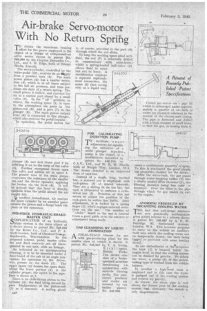
TO . obtain the maximum braking effort for the power employed is the object of a design of compressed-air servo motor shown in patent No. 549,300 by the Clayton Dewandre Co., Ltd., and S. H. Edge, both of Titanic IVorks, Lincoln.
The servo-cylinder, controlled by the
brake-pedal (10), receives its air ply from a pressure tank (3). The main. power piston (2) has a smaller extension (4) which is at all times subject to the full air pressure, and thus performs the duty of a return spring. The small piston is hollow, and conveys the air to a central port closed by a small valve (5). In_ the " off " position, as shown, the working space (1) is open to the atmosphere via ports in the piston-rod (9), and a port (7) in the plunger (8). The main power output lever (6) is connected to this plunger, which also receives the pedal impulse.
In operation, the pedal moves the plunger (8) and first closes port 7 by ablittting it on to the stem of the valve (5). Further movement forces open this valve and admits air to space 1. The greater area of the main piston .avercomes the resistance of the smaller one And the device operates, applying the brakes via the lever (6). It will be goticed that this lever is directly °partible from the pedal should the air supply fail.
;p another embodiment, air reaches the main cylinder by an annular space outside the piston and a flange 'takes the place of the extension.
ONE4PIECE HYDRAULIC-BRAKE MASTER UNIT
SIMPLIFICATION of an hydraulic brake system is the main object of a device shown in patent No. 549,333 by the Rover Co., Ltd., and P. A. Scott-Iversen, both of Chesford Grange, Kenilworth,Warwickshire. In the proposed scheme, pedal, master cylin
der and fluid reservoir ,are all incorporated in one unit, with no linkage. As indicated an an accompanying " drawing, it is to be mounted under a
floor-bard of the cab at an angle convenient for operation by the driver, who, presses on the knob (1). The. upper space (2) 'houses the spare fluid, whilst the lower portion' (4) is the cylinder proper; the outlet to the pipelines is shown at..5. There is no close-fitting piston in the -cylinder (4), the fluid being moved by pare displacement of the piston-rod (7) as it descends. A sealing gland
is, of course, provided, in the part (6) through which the rod slides.
To keep the working space filled with fluid, the rod (7) is internally drilled' to communicate with cross-holes,a whilst a spring-loaded ball-valve (3) allows fluid to enter but not to leave. A modification employs a separate replenishment connection, the space (2) then acting only as a liquid seal.
poR CALIBRATING INJECTION PUMP
facilitate, exact adjustment for equalizing the deliveries of a multi plunger injection. pump is the object of a modification described in
c patent No. 549,210, by
CAN.. Ltd., and W. .E: W. Nicolls, both of Warple Way, London, W.3. The device detailed is an improved form of rack-bar.
Instead of a single, long, toothed bar, a screwed rod is employed, with rack-pieces (3) at spaced intervals. They are a sliding fit dn the bar, but each is bifurcated to embrace a cylindrical hut (2). Rotation of this nut serves to adjust the position of tbe rack-piece to within fine limits. After adjustment, it is locked by a spring finger (1), which engages external serrations on the nut. The number of " clicks" beard as the nut is rotated forms a good guide as to the amount ofadjustment being made.
GAS CLEANSING BY LIQUID ATOMIZATION
AFINAL-STAGE 'dewier for use with gas-producing plant for the smaller sizes of vehicle is shown in patent No. 549,345 by F. A. Irving, Kirk Ii ngton, 549345 &dale. Yorks.
-The device consists of a 'wateraperateit scrubber functioning i n c,onjunction with suitable filtering media. The associated producer and cooler are Covered by •an earlier patent, No. 542,906.
Cooled gas enters via *a. pipe (3) which is submerged tirider approximately a qnartee of aninch of water (or chemical solution) in the bottom of the cleaner-unit casing.
.. The pipe is flattened and .drilled with a large number.of small holes, so that the gas, in issuing from i.
raises a considerable quantity' of spray. To this is attributed the -good. cleans. ing properties claimed for the device..
After the water-bath, the gas passes through water-trapping baffles (2)intb a closely packed filter chamber' (I), -the filtering material being fine coke or horsehair, Over the filter is the pipe through. which the gas wakes its exit to the engine:
AVOIDING FREEZE-UP BY DECANTING COOLING WATER
THE fact that anti-freeze mixtures are now practically unobtainable . gives added interest to a scheme shown in patent NO. 549,097 by A. P. W.
• Biirridge, 82, Sutherland Avenue, London, W.9. This inventor proposes to carry on 'the vehicle an auxiliary tank into which the cooling water can be temporarily. stored, the tankbeing lagged or provided with some heating device. •
In one embodiment of the invention the tank (I) is located_ below the engine level, so that the cooling system can be drained by gravity: To return the water, a pump e (2) of the petrolraising type is Worked from the vehicle battery. In another a high-.revel tank is employed and in this 'case the water is pumped out of the. cooling system and returns by gravity.
, As drawn, the drain pipe is well aboVe.the lowest part of the cooling ' -system.' but, obviously; the sketeh only diagrammatic.