


RADIATOR-CONDENSER DESIGN.
Page 28
If you've noticed an error in this article please click here to report it so we can fix it.
A Résumé of Recently Published Patents.
IT IS VERY often possible by study of a series of patent specifications which have been taken out in connec tion. with any specific invention to obtain some useful and fairly accurate data as to difficulties which are being experienced in the course of developing the original idea, and one can trace with considerable interest the modifications imposed by practical working conditions on the -first more or less theoretical notions ofthe inventor. A case in point seems to be exemplified in specification No. 190,124, which has been taken out by S. W. Rushmore, the inventor of that system of cooling for motorcar engines in which the water in the cylinder jackets is at boiling point, the steam formed being condensed in what corresponds to the radiator in an ordinary cooling system, the water of condensation being returned for circulation again. In such a system the water and the steam from the engine jacket are discharged into a separating chamber in the bottom of a condenser, the water being returned into the engine jacket and the steam rising in the tubes of the condenser or radiator.
In a former patent obtained by this inventor it was taken for granted that the operation of a system of this kind could efficiently be carried out using such radiators as are already customarily employed on motor vehicles. In practicril operation, however, certain inherent defects of radiators of the standard type as employed for that purpose have been disclosed.
The primary difficulty is that the cooling fan induces a much heavier blast of air in the central portions of the frontal area of the radiator or condenser than at the sides. Consequently, the central portions are capable of radiating much
• more heat and condensing much more steam per unit of cooling area than are the sides, but as the side passages are designed to have the same or even less flow resistance than the central portions, the result is that where the relatively frictionless, weightless steam is substituted for water the balance of -flow is upset.
Apparently it so happens that long before the total volume of steam to be condenseckbecomes great enough to tax the cooling capacity of the condenser as a whole the inferior capacity at the sides will be overtaxed. As a result, there remains in the central portion of the condenser a body of air which is .sup-; ported from below by up-flowing steam arid sealed in above by steam which has risen from the sides. The air thus trapped stays trapped, practically excluding the steam which might otherwise flow in from both top and bottom.
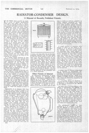
These difficulties are claimed to be overcome by the use of a condenser the design of which is exemplified in principle by the one which is illustrated herewith. In that condenser each vertical tube is plugged at the top, a small central hole being bored in the plug, the size of the hole being determined by the conditions which may make it desirable, for example, that the size of the holes in the plugs for the side tubes should be less than those in the central tubes. The desired effect is that the vent must be B44
of such a size that after the air has been gradually expelled from the ,side tubes, so that live steam begins to .flow out of their tops, the flow resistance at the vent will be sufficient to pile up a slight back pressure. Such back pressure necessarily takes effect as an upward pressure in the central tubes, sufficient to maintain the larger volume of steam which the central area will condense on account of the improved cooling effect due to the location of the fan. In that manner is the balance of flow preserved and the efficiency of the condenser unit as a whole improved.
Other Patents of Interest.
An interesting construction of headlamp, designed to diminish dazzle effects, is described in specification No. 208,574, by A. S. Ward. There are two bulbs-to the lamp; the upper one is surrounded by its own reflector, which tends to throw the light of the lamp in a downward direction. A portion of its reflector is cut away to allow some of that
light to strike an ordinary parabolic or similar reflector occupying the usual position at the back of the lamp. The _lower bulb projects almost vertically from the bottom of the lamp, and its light is reflected in part from the reflector of the other bulb and in part from the main oflector at the rear. The front of the lamp is in three parts; the upper portion is vertical, the middle portion slopes downwardly and to the rear, and the lower portion is also vertical. The light rays are thus divided into three portions—those passing through the top portion of the front being directed in an upward and horizontal direction, those passing through the central part downwardly, and those in the lowest part horizontally.
A simple method of retaining valve springs in place on the stems is described by C. T. Barnes in specification No. 208,423. The valve spring washer has dependent lugs, which support on transverse pins a pair of small bell-crank levers, designed .80 that their vertical arms tend always to close in upon the valve stem. The latter is tinned down near its lower end to form a collar, with which the ends of these levers engage, thus holding the collar and spring in piece. To remove the spring it is only necessary to lift upwards at the outer ends of the bell-crank levers, disengaging the lower ends from the collar on the stems, when both springand washer can be removed.
A simple form of silencer is described by J. Stirling in specification No. 208,651. It is a simple casting in halves, streamline in form and with radiating fins on its exterior surface. Inside are a number of baffles formed of transverse ribs, which are themselves streamline in cross-section.
A connecting device to facilitate a coupling of a tyre inflator to the valve is described in specification No. 208,581 by W. Turner.
• An inner tube of peculiar design is the subject of specification No. 20808, by J. %riven. it has thick walls, and its outer profile, before inflating, is very much the same as the inner profile of the • outer cover. There are grooves formed on the outer surface of the tube, on that part of it which corresponds to the tread of the tyre. Internally, the tube is thickened wherever these grooves occur. It is claimed that this construction has the effect of causing a tube to cling to the inner surface of the cover and reduce the tendency to creep.
The splashguard which has been patented by " 3. R. Stubley in specification Nb. 208,654 is a plain annular disc of 'flexible material, this being loosely carried in a supplementary grooved rim which is carried at the side of the wheel. There is sufficient clearance between the inner surface of the splashguard and the bottom of that groove to allow of the splashguard lagging behind the wheel so that the central point of its contact with the ground is opposite the rearmost point of the contact of the tyre with the ground, thus increasing its effectiveness.