


Patents Completed.
Page 34
If you've noticed an error in this article please click here to report it so we can fix it.
Knight Modification. Flexible Couplings. Hydraulically Operated Valves.
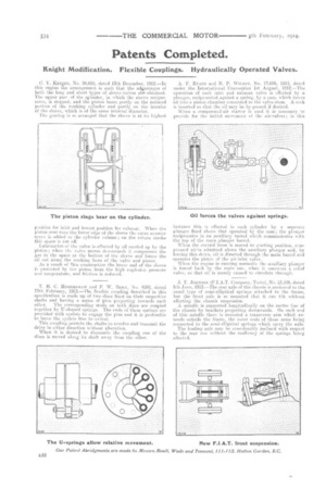
C. Y. lilt-101IT, No. 28,695, dated 13th December, 1912.—In this engine the arrangement is such that the adriantages of both the long and short types of sleeve-valves al.4 obtained. The upper pail of the cylinder, in which the sleeve reciprocates, is stepped, and the piston bears partly on the reduced portion of the working cylinder and partly on the interior of the sleeve, which is of the same internal diameter.
The gearing is so arranged that the sleeve is at its highest position for inlet and lowest position for exhaust. When the piston over-runs the lower edge of the sleeve the extra annular space is added to the cylinder volume ; on the return stroke this space is cut, off.
Lubrication of the valve is effected by oil carried up by the piston ; when the valve moves downwards it compresses the gas in the space at the bottom of the sleeve and forces tho oil out along the working faces of the valve and piston. As a result of fltis construction the lower end of the sleeve is protected by the piston from the high explosion pressure and temperature, and friction is reduced.
1, H. C. HOMERSHAM and F. W. BERK, No. 4080, dated 17th February-, 1913.—The flexible coupling described in this specification is made up of two discs fixed on their respective shafts and having a series of pins projecting towards each
other. The corresponding studs on both discs are coupled together by U-shaped springs. The ends of these springs are provided with eyelets to engage the pins and it. is preferable to leave the eyelets free to swivel.
This conpling permits the shafts to revolve and transmit the drive in either direction without alteration.
When it is desired to dismantle the coupling one of the discs is moved along its shaft away from the other.
A. F. EVANS and R. P. WILSON, No. 17,606, 1913, dated under the International Convention 1st August, 1912.—Thu operation of Each inlet and exhaust valve is effected by a plunger, reciprocated against a spring, by a cam, which forces oil into a piston chamber connected to the valve-stem. A cock is inserted so that the oil may be, by-passed if desired.
When a compressed-air starter is used it is necessary to provide for the initial movement of the air-valves ; in this instance this is effected in each cylinder by a separate plunger fixed above that operated by the cam; the plunger reciprocates in an auxiliary barrel which communicates with the top of the main plunger barrel.
-When the control lever is moved to starting position, cernpressed air, is admitted above the auxiliary plunger and, by forcing this down, oil is directed through the main barrel and operates the piston of the air-inlet valve.
When the engine is running normally the auxiliary plunger is forced back by the main one, when it uncovers a relief valve, so that oil is merely caused to circulate through.
3. Y. JOHNSON (FIAT. Company, Turin), No. 13,186, dated 6th June, 1913.—The rear axle of the chassis is anchored to the usual type of semi-elliptical springs attached to the frame, but the front axle is so mounted that it can tilt without affecting the chassis suspension.
A spindle is supported longitudinally on the centre line of the chassis by brackets projecting downwards. On each end of this spindle there is mounted a transverse arm which extends outside the frame, the outer ends of these arms being connected to the semi-elliptical springs which carry the axle.
The leading axle may be considerably inclined with respect to the rear one without the resiliency of the springs being affected.