


Drivers &Mechanics
Page 32
Page 33
If you've noticed an error in this article please click here to report it so we can fix it.
Light up your Lamps at 3.53 on Thursday ; 5.55 on Friday ; 5.56' on Saturday; 6.0 on Monday ; 6.2 on Tuesday ; 6.4 on Wednesday.
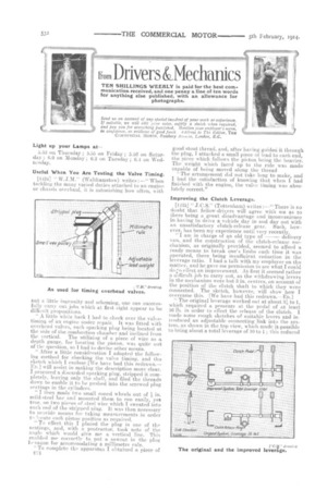
Useful When You Are Testing the Valve Timing.
L14341 " W.J.31." (Walthamstow) writes ;—" When tackling the many varied duties attached to an engine or chassis overhaul, it is astonishing how often, with Put a little ingenuity and scheming, one can successfully carry out jobs which at first sight appear to be difficult propositions.
" A little while back I had to chock over the valvetiming of an engine under repair. It was fitted with overhead valves, each sparking plug being located at the side of the combustion chamber and inclined from the vertical. The utilizing of a piece of wire as a depth gauge, for locating the piston, was quite oiO of the question, so I had to devise other means.
" After a little consideration I adopted the following method for checking the valve timing, and the sketch which I enclose [We have had this redrawn.— En.] will assist in making the description more clear. procured a discarded sparking plug, stripped it completely, leaving only the shell, and filed the threads down to enable it. to he pushed into the screwed plug seating's in the cylinders. " I then made two small coned wheels out of in. mild-steel bar and mounted them to run easily, yet true, on two pieces of steel wire which T sweated into each end of the stripped plug. It was then necessary to provide means for taking measurements in order te locate each piston position as required. " To effect, this I placed the plug in one of the seatings, and, with a. protractor, took note of the angle which would give me a vertical line. This enabled me correctly to put a sawcut in the plug hexagon for accommodating a millimetre rule.
"To complete the apparatus I obtained a piece of
good stout thread, and, after having guided it through the plug, I attached a small piece of lead to each end, the piece which follows the piston. being the heavier. The weight which faced up to the rule was made capable of being moved along the thread
The arrangement did not take long to make, and I had the satisfaction of knowing that when I had finished with the engine, the valve timing was absolutely correct."
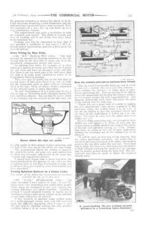
Improving the Clutch Leverage.
[14:35j " J. C.S." (Tottenham) writes :—" There is no doubt that fellow-drivers will agree with me as to there being a great disadvantage and inconvenience in having to drive a vehicle day in and day out with an unsatisfactory clutch-release gear. Such, however, has been my experience until very recently. " I am in charge of an old type of delivery van, and the construction of the clutch-release mechanism, as originally provided, seemed to afford a ready means to break one's limbs each time it was operated, there being insufficient reduction in the leverage ratio. I had a talk with my employer on the matter, and he gave me permission to see what I could doZo effect an improvement. At first it seemed rather a difficult job to carry out, as the withdrawing levers in the mechanism were but 3 in. centres, on account of the position of the clutch shaft to which they were connected. The sketch, however, will show how I overcame this. [We have had this redrawn.—ED.] " The original leverage worked out at about :3l2 to 1, which required a pressure at the pedal of at least 56 lb in order to effect the release of the clutch. I made some rough sketches of suitable levers and introduced an adjustable connecting link into the system, as shown in the top view, which made it-possible to bring about a total leverage of 10 to 1; this reduced
the pressure necessary to release the clutch to 20 lb. I had the levers forged by a local blacksmith and the mild-steel bar 1 procured from a steel merchant. With the assistance of a mate the rig was fitted up in a very satisfactory manner, " The improvement was quite a revelation to both my employer and myself. The clutch is smooth and easy in working, and is not tiring even after many hours continual use.
Perhaps you will be interested to hear that I was awarded a certificate in last year's C.M.U.A. Parade petrol examination, and also a third prize for general upkeep."
When Fitting Up Rear Axles.
[1436] " R.T." (Bedford Hill) writes One may
perhaps be excused for drawing attention to the following hint by the fact that in many jobs it is the apparently unimportant details that coo ii.
In erecting rear axles, for example, it is often taken as a. matter of course, provided the bevel gears are not worn and have no damaged teeth, and also that there is not too much play in the ball raoes, that the axle is in quite good condition to admit of its b-eing finally fitted in position.
" This view may be partly due to the fact that in certain types of axle-cases there is no way of holding the component parts in place without enclosing them in the case, when, of course, further inspection of the internal parts is quite impossible. " In such circumstances it is a good plan to use a clip or clips as illustrated in the enclosed sketch [We have had this redrawn.—Em] so that the parts, which in the ordinary way are secured by the axle-case, can ho held rigidly in their proper relative positions, and yel half of the case can be left off for the time being. " The arrangement allows the erector to examine the wheels for mesh, end play, etc., and enables him to effect any necessary adjustment in the most convenient and expeditious manner.
" I myself have found, that in many instances, the noises produced by the gearing of tear axles are due to nothing more. or less than haphazard erecting, and could have, been prevented by some such method as I have described."
Turning Spherical Surfaces on a Centre Lathe.
The sender of the following COMmunication. lees been awarded the 108. pthe this week.
[1437] " O.A.G." (Huddersfield) writes On
many occasions I have noticed in your D. and pages some vary interesting and useful lathe attachments mane by mechanics to get over various machining difficulties with plant available. Possibly a method I myself adopted reeently to enable me to machine a concave and convex surface on an ordinary centre lathe will prove of interest. "I had occasion to machine some replace parts of a badly-damaged torque tube and ball universal joint, the difficulty appearing when I came to turn the ball and its spherical seating, the only machine available being a 1.2 in. centre lathe. How the concave and convex surfaces were turned.
" The rig which I eventually fitted up, and of which I send you a sketch—[We have had this redrawn.--En.]—enabled me, however, to make quite a satisfactory machining job. The top portion of the sketch shows the attachment for turning the -concave surface, the lower part depicts the ball being machined. The diagram underneath each lathe illustrates the path of the cutting Wei for each case. " There was not a great deal of trouble in making the two attachments ; they merely consisted of flat mild-steel stripe, the section being -).; in. by 1 in. I mit off six lengths to give the necessary travel, and the base of the angle-pieces I drilled out-a in. diameter, two hole-s in each, and the, plain ends were drilled. out The swivelling connecting rods, two in number, were drilled out and tapped ?, in. Whit, at each end, the centres being carefully marked out equal to the radius of the ball and spherical seating, i.e., 4 ins. Permitting these to swing at the end of each angle-piece enabled the necessary arc of the cutting tool to be effected.
" It will be seen, on referring to the drawing, that for either machining operation, one angle-strip is bolted to the loose headstock of the lathe, and another piece to the top slide under thetool rest. Cross-feed only is used, the transverse feed being free altogether so that without. touching the handwheel the carriage may be readily pushed along the lathe-bed. The cutting-tool may then be made to follow the required circular path."