


A Single-plunger Injection Pump
Page 58
If you've noticed an error in this article please click here to report it so we can fix it.
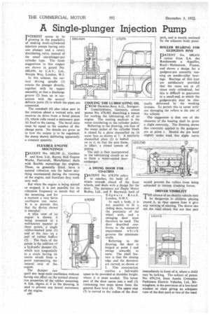
INTEREST seems to be I growing in the possibility of making multi-cylindered injection pumps having only one plunger and a rotary distributing valve, instead of the usual one-plunger-per cylinder type. The latest suggestions in this respect are shown in patent No. 680,494, by C.A.V., Ltd., Warple Way, London, W.3.
In this scheme, the vertical driving spindle (1) rotates the plunger directly, together with its tappet assembly, so that a discharge groove (2) lines up in succession with the several delivery ports (3) to which the pipes are connected.
The camshaft (4) also takes part in the rotation about a vertical axis, and receives its drive from a bevel pinion (5), which rolls round a stationary gear (6) fixed to the casing. The bevel ratio must be equal to the number of discharge ports. No details are given as to how the output is to be regulated, the pump shown .deliiiering apparently a constant quantity.
FLEXIBLE ENGINE MOUNTINGS
PATENT No. 680,298 (L. Gardner and Sons, Ltd., Barton Hall Engine Works, Patricroft, Manchester) deals
with flexible mountings for engines. These, as generally fitted, have 'a
natural vibration rate far below anything encountered .during the running of the engine, and therefore they work
very well. , . , But when the engine is being started or stopped, it is just possible for its vibration frequency to match that of the mounting, and for a moment a very fierce oscillation can occur. lt is to prevent this that the device shown is intended.
A plan view of an engine is shown, it being mounted in a well-known manner at three points,a single rubber-bushed joint (1) and at the rear on a pair of rubber buffers (2). The basis of the patent is the addition of a hydraulic damper (3), whiCh 'acts tangentially to a circle haing its centre struck from a point representing the natural axis of the . engine.
The damper can quell any large-scale oscillation without having any. effect on the normal absorptive properties of the rubber mounting. A link, shiiwn at 4 in the drawing, is used to prevent any lateral movement of the engine.
s40 COOLING THE LUBRICATING OIL VROM Daimler-Benz A.G., Stuttgart" Unterttirkheim, Germany, comes patent No. 678,902 describing a means for cooling the lubricating oil of an engine. The cooling medium is the water circulating in the cylinder jacket..
The unit is then incorporated in the lubricating circuit so as to form a water-cooled heatexchanger. .• A SWING DOOR FOR COACHES
PATENT No. 678,976 refers to coaches, the body of which extends ,ahead of the front wheels, and deals with a design for the door. The patentees are Duple Motor Bodies, Ltd. and P. Hayward, both of
Edgware Road, London, N.W.9.
In such a body, it is not possible to fit a sliding door, because of the proximity of the wheel arch, and a swinging door must therefore be used. The door described conforms to the statutory requirement which governs the minimum width.
Referring to the drawing, the door is hinged at point 1 and swings inwardly to open. The chief feature is that the closing edge and the doorpost are curved, as shown at 2. This construction enables a full-width space to be provided at shoulder height, where it is most needed. The lower part of the door opens into a well (3) containing two steps down from the general floor level (4). The upper step (5) is curved to the radius of the door path, and is mostly enclosed by the adjacent body panel.
ROLLER BEARING FOR GUDGEON PINS
PATENT No. 680,4/6 comes from S.A. des Roulements a Aiguilles, Rued M a lmai son, France, and shows a design for a gudgeon-pin assembly running on needle-roller bearings. Bearings of this type are satisfactory provided that the races are at all times truly cylindrical, but this is difficult to guarantee in a small-end, in which the gudgeon-pin may be elastically deformed by the working stresses. To permit this to occur without damaging the rollers is the aim of the scheme.
The suggestion is that one of the elements of the hearing shall be given a slight convexity. The drawing shows this convexity applied to the gudgeonpin at point J. Should the pin bend slightly under load, this slight curve would prevent the rollers from being subjected to intense crushing forces.
DRIVER VISIBILITY
THE silence-of-an electric vehicle may be dangerous to children playing round it, as they cannot hear it give any warning of starting. The driver can see the road ahead, but not that part
immediately in front of it, where a child may be lurking. The subject of patent No. 679,214, from Austin Crompton Parkinson Electric Vehicles, Ltd., Birmingham, is the provision of a low-level window or visor giving an adequate view of the first yard or two of the road.