


Patents Completed.
Page 26
If you've noticed an error in this article please click here to report it so we can fix it.
A Novel Change-speed Gear.
A. B. Jones and C. L. Jones, No. 27,459, dated December, 1911.-1n the gearbox illustrated in the accompanying drawings, the driving shaft enters at the middle of the left-hand side. A series or countershafts is symmetrically spaced around the driving shaft ; they are mounted in a separate framing which can be rotated about the driving shaft as a centre. The countershafts are all
driven from the driving shaft by chain gearing with a speed reduction from each shaft to the next, so that all the countershafts are running continuously, each one at a lower speed than the previous one. A reverse countershaft is geared to the last forward countershaft at the end of the train. The driven shaft is displaced from the centre line of the driving shaft by the same amount as the countershafts. The rotating frame carrying the countershafts is moved round, and brings each countershaft in turn in alignment with the driven shaft ; suitable clutch mechanism is provided to lock the two together and transmit the drive with any required reduction.
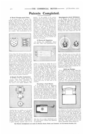
A Simple Paraffin Carburetter.
F. R. Davis, No. 24,106, dated 31st October, 1911.—This carburetter is divided into three chambers, of which the lower is the nozzle chamber; this
chamber has two nozzles, one for petrol and one for paraffin. In addition it tapers upwards and opens into the mixing chamber, in which there is fixed a spiral baffle. The object of the baffle is to cause the mixture to travel in a circular path in close contact with the wall of the mixing chamber. Preferably a double helix is provided, so that there is a path starting opposite each of the
nozzles. In the middle of the mixing chamber, that is the hottest portion, the spiral baffles are cut away. The exhaust is made to circulate around this second chamber, which collects heat from it by ribs or flanges, and transmits it to the mixture. The induction pipe is connected at the top. When cleaning the carburetter, this pipe is disconnected, and the spiral baffle is drawn out complete, this construction giving great accessibility to all parts. In addition it provides easy adjustment in varying the size of the central chamber by cutting away the baffles. Air is admitted to the bottom around the jets by suitable hitand-miss valve ports.
A Heavy-oil Vaporizer.
S. Crosbie, No. 26,337/1911, dated 15th May, 1912.—This specification de
scribes a vaporizer in which the oil is fed in from the left-hand side, as shown in the drawings, through tubes having conical ends which are revolved at high speed by suitable motors. The oil is atomized on leaving these tubes and travels along the mixing chambers, being heated by an external source at the same time. The accompanying draw ing shows a plan of the apparatus in which the auxiliary burner shown at the centre is fed with oil under pressure; the products of combustion from this burner pass away at each end of the chamber.
Ensuring a Cool Piston.
T. W. Sheppard and F. W. Sheppard, No. 10,314, dated 1st May, 1912.—In many internal-combustion engines are unnecessarily low compression is used. because excessive local heating at the top of the piston may cause pre-ignition. According to the present invention this overheating is prevented by oil cooling the piston-head. A jot of oil is directed on to the outer side of tho piston-head, and the surface receiving it is so shaped
that the oil is evenly distributed over the whole piston without any splashing or spattering.
Splashguards which Withdraw.
C. H. Nichols, No. 24,313, dated 2nd November, 1911, Patent of Addition to No. 29,587 of 1909.—The two accompanying figures show this mudguard as a complete attachment for a wheel, and also give a view of a wheel with a mudguard u». Two arms are clamped to the spokes of the wheel, and these carry a flanged ring on which is a further ring carrying the main framework and the guard. The first ring revolves with the wheel, but the second ring is held from turning by a spring at the top. The frame carrying the guard has two curved slots working on pins, the curve of each slot being struck from the other pin as a centre. When the guard meets an obstruction it swings about the foremost pin as a centre, and the frame rises, carrying the guard with it inside the circumference of the wheel.
Built-up Pistons. W. S. Knowles, No. 11,077, dated 9th May, 1912.—According to this invention the piston for an internal-combustion engine is made in two parts, one forming the head of the piston and receiving the gudgeon pin, and the other the sleeve of the piston. The head is conveniently formed of steel, and is convex on its upper side. Two oppositely-disposed lugs
are formed on the under side and these are bored out to reoeive the gudgeon pin. The sleeve, which may be of steel or cast iron, has its walls thickened and turned down to receive the piston rings. These thickened portions are also bored to receive the gudgeon pin, which is of sufficient length to engage the sleeve at each side. The head is sunk into the sleeve, preferably being pressed in.