


A German Torsion-spring System I NTEREST in torsion-springing systems seems
Page 66
If you've noticed an error in this article please click here to report it so we can fix it.
to be growing, and patent No. 424,452 shows a design of this type. The patentee is Dr. Ing. Porsche, of Kronenstrasse 24, Stuttgart-Untertfirkheim, Germany. This system is specially applicable to swinging half-axles, and the novel feature consists of the placing of the torsion springs approximately in the swinging axis of the half-axles.
The accompanying drawing shows a plan view of the layout, in which a universally jointed half-axle carries a rigid strut (1) extending from the brake disc to the springing arrangement. This consists of a central spring rod (4)—journalled in bushes on a frame bracket—to the outer end of which the strut is splined. The inner end (5) of this rod is welded on to a stout helical spring (3) which is anchored to the frame at the outer end (2).
In operation, rising of the wheel sets up a torsional stress in the rod (4) and a bending stress in the helical spring.
Several other designs are shown in the patent, in which torsion rods alone are employed to meet the springing requirements.
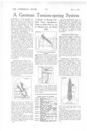
Keeping Injection Nozzles Cool.
THE high speeds of modern oil engines give rise to many problems in connection with overheating of the injection arrangements, and in patent No. 424,417, Daimler-Benz A.G. of
Stuttgart-lintertfirkheim, Germany, discloses an improved assembly, the object of which is to screen the nozzle body from the high combustion-chamber temperatures.
In the drawing, 4 is a "wet sleeve," that is, it is open at its middle to the cooling water space (5). In this sleeve is housed the nozzle body (1), which is surrounded by a cap-nut (2). The essence of the invention is a conical copper washer (3), which is pressed into contact with the water-cooled sleeve and, owing to its high conductivity, effectively prevents the body reaching extreme temperatures.
A further design is shown in which the copper washer itself is in actual contact with the cooling water ; this is intended for engines the speed of which is in excess of 2,000 r.p.m.
B48 Fuel Injection for Spark-ignition Engines.
ASYSTEM using an injection pump instead of a carburetter on a sparkignition engine is shown in patent No. 421,576 by M. G. Chandler, 1,637, Euclid Avenue, Flint, Michigan,
The main objective seems to be the breaking up of the fuel into the finest possible spray, and to this end injec tion nozzles (1) are mounted immediately under the inlet valves, as clearly shown in the accompanying drawing. Fuel is supplied by a metering pump, but at a lower pressure than that used in oil engines. The patent describes the nozzle construction in detail; this consists of a poppet valve with a laminated head, the laminations forming the closing spring. The fuel pressure lifts the laminations and, in passing, the fuel is broken up into a fine mist. Reference is made to a previous patent, No. 327,219, describing the pump mechanism.
A Dual-purpose Brake Facing.
AN ingenious scheme is suggested in patent No. 424,726 by the Raybestos Corporation, Bridgeport, U.S.A. The specification states that whilst high-servo brakes require a facing with a friction coefficient of 0.3, hydraulic brakes work better with a facing of a higher frictional value, such as 0.6. This necessitates an agent or ,repairshop 'keeping a double stock of facings, and to remedy this state of affairs it is proposed to manufacture the facings with a different grade of surface on each side, so that the repairer could choose the side most suitable for the job.
Injection-pump Improvements.
FROM C. B. Redrup, and the Bristol Tramways and Carriage Co., Ltd„ Clare Street House, Bristol, comes patent No. 423,976, which describes a form of pump in which the quantity delivered is constant, irrespective of the engine speed. In this design, the plunger (3) slides in a cylinder (4) which itself can move in the casing. The cylinder has a conical upper end, which makes contact with the seating (1) on the pressure stroke; the suction
stroke occurs with the cylinder away from the seating and open to the passage (2).
Operation is by an eccentric, so that the stroke of the tappet (7) is constant. Output regulation is obtained by limiting the movement of the plunger by interposing an abutment member (5) under a flanged collar (6). By this method the point of cut-off remains -the same whatever the value of regulation.