


Four Wheels in Line for Mobile Cranes
Page 36
If you've noticed an error in this article please click here to report it so we can fix it.
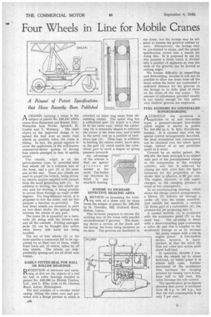
A Résumé of Patent Specifications that Have Recently Been Published ACHASSIS carrying a crane is the subject of patent No. 546,241 which comes from Ransomes and Rapier, Ltd., Waterside Iron Works, Ipswich, R. Crafter and T. Worsnop. The chief object of the improved design is to spread the load over as many road wheels as possible when the crane is lifting, In fact, the patent appears to cover the application of the well-known commercial-motor system of having four wheels arranged in line, to mobile cranes.
The chassis, which is of the petrol-electric type, is provided -with four wheels (4) on a common axis at the front, and a pair -(2) of the same size at the rear. These rear wheels are used to propel the vehicle, being driven by electric motors supplied with current from the mail generating unit (1). In addition to driving, the rear wheels are also used for steering, it being possible to swivel them through an angle of-360
• degrees. For long-distance travel, it is proposed to tow the outfit, and for this purpose a drawbar is provided. The four front wheels are mounted in pairs on two short shafts, the springs being between the wheels of any pair.
The crane jib is mounted on a turntable (5) along with the driver's cab and all the controls. Folding outrigger jacks (3) can be brought into action when heavy side loads are being handled.
The use of four wheels (4) at the front enables a comerwise lift to be supported by at least two of them, whilst front loads are, of course; taken by all four wheels. The wheels are independently sprung and are all fitted with brakes.
EASILY FITTED SEAL FOR BALL OR ROLLER BEARINGS
D ETENTION of lubricant and exclu
sion of dirt are the objects of a seal for ball or roller bearings detailed in patent No. 546,260 by British Timken, Ltd., and L. Ellis, both of 65, Cheston Road, Aston, Birmingham.
The seal consists of a circular metal casing fitting the outer race and provided with a flange portion to which is
attached an inner ring made from oilresisting rubber. The metal ring has a cylindrical part (1) which is a close fit in the outer race, whilst the rubber ring (3) is internally shaped to embrace the corner of the inner race, and is held, in the metal case by a number of bentdown lugs (2). These lugs, in addition to holding the rubber insert, leave slots in the part (1) which enable the cylindrical part to exert a degree of spring pressure outwards
An advantage of the scheme is that no special grooves are needed in the races. The device can therefore be fitted to any standard bearing.
SCHEME TO INCREASE EFFECTIVE BRAKING AREA
AMETHOD of increasing the braking area of a drum and its shoes forms the subject of patent No. 546,215 by H. Thomley, 552, Halliwell Road, Bolton, Lancs.
This inventor proposes to serrate the working face of the drum with parallel circumferential V-grooves. The drawing shows a section of the drum and the facing, the latter being mounted on its shoe. The grooves are machined in the drum, but the facings may be left . plain to assume the grooved outline by wear. Alternatively, the facings may be pre-formed to shape, and the patent specification covers also a means for doing this. It is proposed to use for this purpose a drum which is divided into a number of segments so that the ends of the grooves can be formed as cutting edges.
We foresee difficulty in assembling and dismantling, because it will not be possible to diaw the drum from off the shoes unless the latter are contracted a sufficient distance for the grooves on the facings to be fully clear of those on the drum all the way round. The amount of adjustment provided usually is not nearly enough for this unless very shallow grooves are employed.
FUEL ECONOMY BY CONTROLLED SUPERCHARGING
A LTHOUGH the invention is tiapplicable to oil and two-stroke types, a pressure-charged four-stroke petrol engihe is shown in patent No. 545,900 by A. B. Milo, Stockholm, Sweden. It is claimed that with the special control arrangements described, the most economical fuel Consumption can be obtained over the whole speed range, instead of at one particular speed as is usual.
Covered by an earlier patent, No. 534,161, the basic principle is to subject only part of the precompressed charge to the compression in the working' cylinder, and this is achieved by • closing the inlet valve late; the figure instanced for the proportion of the stroke that is effective is 60 per cent. The engine, however, is still supercharged, as the charging pressure is rated at two atmospheres.
In an accompanying drawing, which shows the charge control arrangements, a blower (5) delivers air through a cooler (3) into the intake manifold. Just outside the manifold, a venturi (2) forms part of a carburetter (4), the pressure-fed jet projecting into it. A normal throttle (1) is connected with the accelerator pedal (7) in the usual way. The air-pump is fitted with a short-circuiting pipe containing a valve (6) and this is coupled to the accelerator linkage so as to increase the pump output with a rise in. engine power. A lost-motion device, however, is incorporated, so that the valve • (6) does not conic into action until about half-load.
In operation, throttle 1 controls the output up to about half-load, at which point it is almost fully open. Further movement of the accelerator then increases the charging pressure by closing valve 6.and, from half to full load, this valve becomes the sole control.
The specification gives figures showing that power is increased from 68 h.p. to 167 h.p., but that the fuel consumption cs up only 7 per cent. •