


A Daimler-Benz Two-stroke
Page 62
If you've noticed an error in this article please click here to report it so we can fix it.
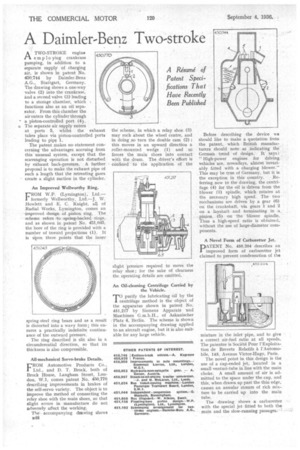
A. TWO-STROKE engine ti employing crankcase pumping, in addition to a separate supply of charging air, is shown in patent No. 450,744 by Daimler-Benz A.G., Stuttgart, Germany. The drawing shows a one-way valve (2) into the crankcase, and a second valve (3) leading to a storage 'chamber, which functions also as an oil separator. From this chamber tho air enters the cylinder through
• a piston-controlled port (4).
is The separate air supply enters at ports 5, whilst the exhaust takes place via piston-controlled ports leading to pipe 1.
The patent makes no statement concerning the advantages accruing from this unusual system, except that the scavenging operation is not disturbed by exhaust back-pressure. A further proposal is to make the exhaust pipe of such a length that the retreating gases create a slight suction in the cylinder.
An Improved Wellworthy Ring.
FROM W.P. (Lymington), Ltd.— formerly Wellworthy, Ltd.—J. W. Howlett and E. C. Knight, all of Radial Works, Lyrnington, comes an improved design of piston ring. The scheme refers to spring-backed rings, and as shown in patent No. 451,045, the bore of the ring is provided with a number of inward projections (I). It is Upon these points that the inner
spring-steel ring bears and as a result is distorted into a wavy form ; this ensures a practically indefinite continuance of the outward pressure.
The ring described is slit also in a circumferential direction, so that its thickness is also compressible.
All-mechanical Servo-brake Details.
FROM Automotive Products Co., Ltd., and D. T. Brock, both of Brock House, Langham Street, London, W.1, comes patent No. 450,770 describing improvements in brakes of the self-servo variety. The object is to improve the method of connecting the relay shoe with the main shoes, so that slight errors in manufacture do not adversely affect the working.
The accompanying drawing shows 1448 the scheme, in which a relay shoe (3) may rock about the wheel centre, and in doing ,so turn the double cam (2) ; this moves in an upward direction a roller-mounted wedge (1) and so forces the main shoes into contact with the drum. The driver's effort is confined to the application of the slight pressure required to move the relay shoe ; for the sake of clearness the operating details are omitted.
An Oil-cleaning Centrifuge Carried by the Vehicle.
rr0 purify the lubricating oil by the 1 centrifuge method is the object of the apparatus shown in patent No. 451,217 by Siemens Apparate und Maschinen G.m.b.H., of Askanischer Platz 4, Berlin. The scheme is shown in the accompanying drawing applied to an aircraft engine, but it is also suitable for any large vehicle.
Before describing the device we should like to make a quotation from the patent, which British manufacturers should note as indicating the German trend of design. It. says : "High-power engines for driving vehicles are, nowadays, almost invariably fitted with a charging blower." This may be true of Germany, but it is the exception in this country. Referring now to the drawing, the centrifuge (4) for the oil is driven from the blower (3) spindle, which rotates at the necessary high speed. The two • mechanisms are driven by a gear (6) on the crankshaft, via gears 1 and 2 on a laysi-saft and terminating in a pinion (5) on the blower Spindle. Thus a high-speed -ratio is obtained, without the use of large-diameter components.
A Novel Form of Carburetter Jet.
PATENT No. 450,204 describes an improved form of carburetter jet claimed to prevent condensation of the
mixture in the inlet pipe, and to give a correct air-fuel ratio at all speeds. The patentee is Societe Pour l'Exploitation de Brevets Relatifs a l'Automobile, 143, Avenue Victor-Hugo, Paris.
The novel point in this design is the use of a cup-ended jet, located in a small venturi-tube in line with the main choke. A small amount of air is admitted to the space under the cup, and this, when drawn up past the thin edge, causes an annular stream of rich mixture to be carried up into the main tube.
The drawing shows a carburetter with the special jet fitted to both the main and the slow-running passages.'-"