


A REAR AXLE WITH' SOME NEW FEATURES
Page 32
If you've noticed an error in this article please click here to report it so we can fix it.
A 114surnd of Recently Published Patent Specifications.
THE specification of the Relay Motor Products Corporation, of Watbash, Indiana, U.S.A., No. 294,511; describes an axle in which the weightbearing member is placed below the centre of the wheel, thus permitting a low platform to be used. The rack
ring and pinion type of drive is employed. Sq far there is nothing new in the design ; the specifica t i o however, says : " The weight .of the vehicle, together with its load, is utilized to assist in driving or retarding the driving wheels in addition to such action normally obtained from the vehicle's source of motive power." This appears to be a somewhat misleading paragraph, as the weight of the vehicle cannot assist in driving the vehicle. We presume that what is meant is that the weight is used to resist the reaction of the drive and braking torque. It would appear that the load-carrying axle, being below the centre of the wheM and being capable of rotation in relation to the springs, is held down by the weight, of the vehicle and its load, thus relieving the springs from all reactional stresses due to driving or braking.
Anti-friction bearings are introduced between the Weight-bearing axle and the sleeve which carries the spring platform. Should the reaction of driving or braking become more than the Weight of the vehicle can resist, rubber pads are provided to resist rotary move-, ment beyond a -predetermined angle. The brakes are operated by means of flexible cables.
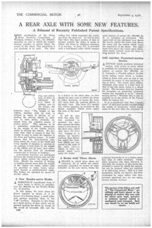
A New Bendix-servo Brake.
A SOMEWHAT complicated form of servo brake is shown in specification No. 294,720, by the Bendix Brtike Co., of America, In this design, the main shoes are joined together as shown at A by means of a floating hinge, a small roller and springs retaining them in the " off " position. Opposite-to this hinge Is a short• section of shoe which can be pregged against the drum by means of the crank or eccentric (3) and the
B48 rolling link which separates the crankpin from the short toe. It will be seen that when this short section of shoe is pressed against the drum, it tends to follow the drum in whatever direction it is moving. A lever (C) is provided with a tall-shaped roller which engages in a hollow in the short shoe, so that should the .shoe tend to follow the drum in either direction, it moves the lever (C) away from the position shown in the main view. The lever (C) carries two rollers engaging in recesses in the thrust members which force apart the ends of the main shoes.
It will be seen from this that friction produced by pressing the short shoe against the dram causes a movement of the short shoe, which acts upon the lever (C), causing it to assume an angular position, thus thrusting apart the members which are connected to the ends of the main shoe s, which, in turn, are moved apart a n apply the brake.
A Brake with Three Shoes.
A BRAKE in which three shoes are" employed, all of which are simultaneously expanded by means of cams rotatable on the axle sleeve, forms the
main feature of patent No. 293,096, by R. A. Crockett, of: Liverpool. The upper half of the left-hand view shows the levers, whilst the lower half shows the cams and the rollers which cause the expansion of the shoes. The righthand view shows the volute cam which, when partly rotated, cause the shoes to beai against the drum.
Still Another Perpetual-motion Device.
A DEVICE which produces perpetual motion, with power to spare which is available for industrial use, forms the subject of patent No. 268,729, by D. Cajander, a Finnish subject. In this device falling water drives a turbine which is fitted with gear so that it can transmit its power to any' machinery it has to drive. The water, after falling, obligingly rises again to a high level so that it can fall again, being in a closed circuit. The inventor does not describe his invention as producing perpetual motion, but describes it as an ' eternal moving device." Whether this is due to: modestyor at the advice of the PatentOffice we cannot say.
It is a significant fact that " tions" of this, kind usually emanate fri the minds of foreigners, which Would point to the fact that the standard of technical knowledge is on a higher plane here than in other countries. Unlike Other inventors who have laboured in this field, the designer of this device has provided a means by which the apparatus can be stopped when not required to be delivering power. This is a wise precaution, which, we observe, has been overlooked by many others who havo invented perpetual mo—we are sorry, eternal moving devices !