


ANOTHER BRITISH BUILT TROLLEY BUS.
Page 26
If you've noticed an error in this article please click here to report it so we can fix it.
Details of a Particularly Interesting Vehicle, Comprising a Leyland Lion Chassis Equipped with English Electric Motor and Body.
WE have, on many occasions, discussed in the columns of this journal the merits of the trolley-bus as, a means for extending tramway routes without the necessity for laying more lines, the cost of which would be prohibitive. For those tramway authorities who are not desirous at the present juncture of 'altogether replacing their tramways system by a more flexible means of transport, the trolley-bus is
proving its utility and, moreover, is able to take advantage of current supplied from existing power stations.
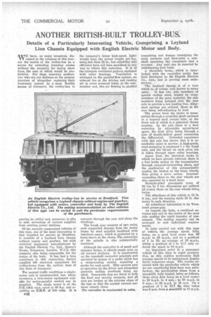
Of the recently constructed vehicles of this type, one of the most interesting is that supplied for service at Bradford, It conSists of a Leyland Lion chassis without engine and gearbox, but with electrical equipment manufactured by the English Electric Co., Ltd., Queen's House, Kingsway, London, W.C.2, this company also being responsible for the design of the body. It has had a long experience in this connection, having supplied tilt electrical equipment for trolley-buses from the earliest days of this form of transport.'
For normal traffic conditions a singlemotor unit is recommended, but, where necessary, a twin-motor equipment suitable for series-parallel control can be supplied. The single motor is of the D.K.106A type, rated at 60 h.p. and requiring an E.M.F. of 500 volts. It is B42 the company's latest high-speed, lightweight type, the actual weight per h.p. being less than 22 lb., but reliability and efficiency have not been sacrificed in any way to obtain this reduction. It is of the interpole ventilated pattern equipped with roller bearings. Ventilation is arranged on the parallel-flow system, an exhaust fan at the driving end causing air to enter screened inlets at the commutator end, this air flowing in parallel currents through the core and along the windings.
The brush gear consists of two units, each supported directly from the motor frame by steel spindles insulated with bakelised paper, which is protected by a brass sleeve at the clamp. The remainder of the spindle is also substantially insulated.
Although the controller is of small and compact design, it affords ample area on all contact surfaces. It is constructed on the camshaft contactor principle and operated by means of a pedal which has a reciprocating motion requiring a stroke for each notch. This ensures ease of operation by the driver and altogether prevents sudden overloads being applied. Renewable tips are fitted to both the fixed and moving contacts, and all arcs are broken at the extreme edges of the tips so that the normal contact surfaces remain clean.
The controller is constructed in units, comprising end frames containing the main contacts and blow-outs, a camshaft operating the contactors and a reverser. Any unit can be removed by withdrawing four bolts.
A rheostatic brake, . which is interlocked with the controller pedal, has been developed by the English Electric Co., Ltd., and is proving most satisfactory.
The Leyland chassis, is of a type which is, of course, well known to many users. It has two side members of special carbon steel, braced by crossmembers of the same material, the side members being humped over the rear axle to provide a low loading line. Alloysteel springs are utilized, those at the rear being self-adjusting to load.
The power from the motor is transmitted through a propeller shaft enclosed in a tapered Steel torque' tube, at the front end of which is a spherical thrust member. In the axle there is a first reduction by adjustable spiral-bevel gears, the final drive being through.a pair of' double-helical gears containing the differential. Extended experience with this axle has shown that it is remarkably quiet in service. A 140-grade, steel stamping is employed f r the front axle, and the thrust on each pivot pin is taken through taper roller bearings.
Apart from the electrical brake to which we have already referred, there is a foot brake acting on the transmission through external-contracting shoes, and the application of this automatically applies the brakes on the front wheels, thus giving a servo action. Internalexpanding shoes on the rear wheels are also operated by a hand lever.
Straight-sided pneumatic tyres of 38 ins. by 7 ins, dimensions are utilized all round, those on the rear wheels being twins.
• The wheelbase of this vehicle is 15 ft. 6 ins., and the turning circle 53 ft. diameter in each direction.
All subsidiary lubrication is by Tecalemit grease-gun.
As regards the body, a combined entrance and exit in the centre of the near' side enables the rapid transfer of passengers. The seating capacity can be arranged to suit individual requirements.
In tests carried out with this type of vehicle, the average speed, fully, laden, on a good level route was 25" m.p.h. to 28 m.p.h., and on a gradient of 1 in 20, an average of 19 m.p.h., whilst a gradient of 1 in 11.7 only reduced the speed to 16 m.p.h.
An important point in a passenger vehicle of this class is rapid acceleraeon, as this enables moderately high average speeds to be maintained, despite fairly numerous stops. The results obtained with the particular vehicle which we are considering have been very satisfactory, the acceleration times from a standstill, fully loaded, being as follows, those given first being on a level route: to 10 m.p.h. in 4 secs.; to 15 m.p.h. in 9 secs.; to 20 m.p.h. in 15 secs. , On a gradient of 1 in 11.7 the time taken was 6 secs, from a standstill to 10 m.p.h.