


WESTINGHOUSE BRAKE IMPROVEMENTS.
Page 12
Page 13
If you've noticed an error in this article please click here to report it so we can fix it.
Simplification of the System and Alteration of Some of the Details.
T"pneumatic braking system de
. veloped by the Wetinghouse veloped by the Wetinghouse
Brake and Saxby Signal Co., Ltd.' has been receiving increasing attention from the uses, and manufacturers of heavy lorries, chars-a-bancs, buses, etc. This system was described in The Commercial Motarbof January 2nd this year, but sincet`that date several improve
ments in design have been made which further experience has. shown to be desirable.
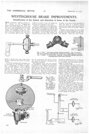
(it will be recalled that the brake rod is operated by the pressure of gases upon a diaphragm of rubber composition clamped between circular dished castings, as shown in the sectional drawing. The construction of this part has been the subject of some criticism by engineers, bus long experience has shown that the diaphragms give abso
lutely no trouble, so that the design has not had to be altered in any way.]
Gases are supplied to the brake cylinders from a steel. receiver, in which they are stored at a pressure of 150 lb. per square inch, the supply being controlled by a driver's valve placed on the steering column. In the older system, an auxiliary quick-release valve was used,
but, by redesigning the driver's valve. this auxiliary has been eliminated and the piping simplified. The diagram shows the new lay-ont as arranged for applying the rear-wheel brakes of a lorry. Minute quantities of burnt gas are taken from one of the engine cylinders on each firing stroke, and are led to the receiver through a nonreturn valve. This valve was formerly placed in the connection which screws into the cylinder, but, owing to heating troubles, it has been found advisable to place the valve in a separate casting secured to the dash under the bonnet at some distance from the cylinder connection.
Another small change has been made in order to obviate blocking of the pipe leading from the cylinder through carbon deposit. This has been amain plished by reducing the bore of the pipe to a minimum, so increasing the velocity of the gases, with the result that the carbon is swept away. The connection with the cylinder was formerly arranged to replace one of the compression taps. This design is still adhered to where possible, but as some engines with detachable heads have no compression taps, an alternative and.ingenious scheme has been adopted. This is shown in the sketch, and it will be seen that it consists of drilling one of the studs which secure the detachable head. The drilled hole communicates wit-h the interior of the cylinder through a small groove cut in the jointing face"of the head.
From the cylinder a pipe runs to the nonsreturn,valve on the dash, and this, in tarn, is connected to the receiver. From the receiver a separate copper tube conveys the gases to the driver's valVe mounted on the steering column, a connection being also taken to a pressure gauge on the dash. • The driver's valve has been entirely redesigned and simplified. Briefly, it is so arranged that the receiver can be gradually placed into communication with the brake cylinders through a port cut in a sliding disc, so applying the brakes smoothly and progressively. A further movement of the lever allows the cylinders to communicate with an exhaust pipe and releases the brakes. An emergency position is also provided which instantaneously supplies gases under 50 lb. pressure to the cylinders. The construction of the valve is clearly shown in the sectional view. The sliding disc is provided with a port, and recess which allow the communications described above to take place when the disc is rotated by the lever. Several haulage contraotors and petrol supply companies have had the Westinghouse system fitted to their vehicles with great success, the drivers being most enthusiastic about the reliability and effectiveness a the air brake. One
The driver's valve (controlling the application of the Westinghouse brakes) on the steering column.
concern, which employs a large number of tractor-lorries, finds that those fitted with air brakes consistently maintain higher average speeds than the others. The labour involved on the part of the driver in braking the heavy vehicles now in common. use is a serious matter, and, of course, this is completely obviated when air pressure is utilized. In addition, this system is particularly suitable for tractor-lorries and trailers, because flexible tubing can be used to convey the gases, thereby avoiding complex rod and cable arrangements. If desired, the Westinghouse system can be so arranged that the brakes on the trailer are automatically applied should it become detached from the lorry. Westinghouse brakes have just been installed on a Buick car for a private owner, this being the first pleasure car to be so fitted in this country. In this case, the design is such that either air or pedal pressure can be used to apply
the rear-wheel brakes, •