


A New Lucas Inductor Magneto
Page 62
If you've noticed an error in this article please click here to report it so we can fix it.
A MAGNETO that gives 12 sparks fl.per revolution forms the subject of patent No. 433,628, by Joseph Lucas, Ltd., and J. A. Laird, both ofGreat King Street, Birmingham. This machine operates on the inductor principle, that is, the flux from a stationary magnet has its path varied by an iron rotor. In the drawing, two bar-magnets (1) are located at top and bottom, their flux encircling the two coils shown (2). • Athree-armed iron rotor (3) by its movement causes six changes of flux values per revolution in each coil core, and owing to the angular displacement of the two coils the flux changes occur at different periods, giving a total of 12 sparks per revolution.
The primary niake-and-break arrangements are those of the usual type, whilst the permissible advance-retard angle is stated to be that of a six-spark machine_
The Latest Gardner Combustion Head. rLAIMED to facilitate cold-starting without the -need for extraneous heating is a design of combustion head which is described in patent No. 433,342 by L. Gardner and Sons, Ltd., and T. J. Gardner, of Barton Hall Engine Works. Patricroft, Manchester. Referring _to the drawing, the piston head contains three depressions, one forming half of the spherical combustion chamber (I), whilst the others (2) are located under the valves, the whole resembling a clover-leaf in plan.
The depressions under the valves are merged together, and communicate with the combustion space, via a tangential restriction (3); this feature is claimed to enSure a high turbulence value at the end of the stroke.
A Pump-assisted Exhaust System.
FROM H. and F. Irwin, the former of 30, The Grove. Benton, Northumberland, and the latter of " The
Riding," Heatherside, Camberley, Surrey, comes patent No. 433,028, in which it is proposed to include in the exhaust system of a vehicle a powerdriven centrifugal pump in order to assist in the evacuation of the gases. The object is to accelerate the gas flow and to maintain a partial vacuum in the manifold between the strokes. Whether the extra power obtained from the engine will exceed that taken by the pump is a question that can only be answered by experiment.
It seems doubtful whether the improved scavenging afforded will materially increase engine efficiency, and it must be remembered that practically no supercharging effect results from the artificial extraction of exhaust gas. n4S Improvements in Twin-wheel Trailing Axles.
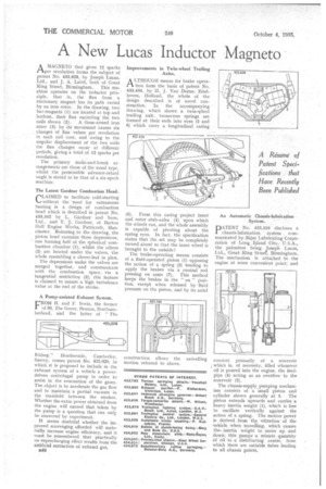
A LTHOUGEI means for brake opera
ti form the basis of patent No. 433,43-4, by H. J. Van Dorne; Eindhoven, Holland, the whole of the design described is of novel construction. In the accompanying drawing, which shows a twin-wheel trailing axle, transverse springs are formed at their ends into eyes (2 and 6) which carry a longitudinal casing
5). From this casing -project inner and outer stub-axles (4) upon which the wheels run, and the whole assembly is capable of pivoting about the spring eyes. In fact, the specification states that the set may be completely turned about so that the inner wheel is brought to the outside!
The brake-operating means consists of a fluid-operated piston (1) opposing the action of a spring (3) tending to apply the brakes via a ,central rod pressing on arms (7). This method keeps the brakes in the "on " poSItion, except when released by fluidpressure on the piston, and by its axial construction allows the swivelling motion referred to above. An Automatic Chassis-lubrication System.
PATENT No. 433,310 discloses a chassis-lubrication : system communicated by_Bijur Lubricating Corporation of Long Island City, U.S.A., the patentees being Joseph Lucas, Ltd., Great King Street, Birmingham. The mechanism is attaehed to the engine at some convenient point; and
consists primarily of a reservoir which is, of necessity, filled whenever oil is poured into the engine, the feedpipe (4) acting as an overflow to the reservoir (2).
The chassis-supply,pumping mechanism consists of a small piston and cylinder shown generally at S. The piston extends upwards and carries a heavy inertia weight (1), which is free to oscillate vertically against the action of a spring. The motive power is derived from the vibration of the vehicle when travelling, which causes the. inertia weight to move up and down; this pumps a minute quantity of oil to a distributing centre, from which there are suitable tubes leading to all chassis points.