


HINTS ON MAINTENANCE,
Page 46
Page 47
If you've noticed an error in this article please click here to report it so we can fix it.
How to Get the Best Out of ES Vehicle, to Secure Reliability and to Avoid Trouble.
CONTRIBUTION8 are invited for this page from fleet managers, drivers, garage foremeneand mechanics, works staff and draughtsmen, and will be paid for on a generous scale. Every system, make, and type of commercial motor vehicle,will be dealt with, and the matter should be written with a view to the ilisclosure of workshop and garage practice in the maintenance of a vehicle—practices which, whilst they may be quite normal, are peculiar to the particular vehicle and may not be generally known to those responsible for its running. Expedients and suggestions for "overcoming roadside and other troubles are covered in the -following page, headed " Roadside and Garage." Communications should be addressed to "The Editor, The Commercial Motor, 7-15, Rosebery Avenue, London, E.C. 1."
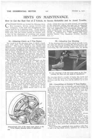
98.—Adjusting Clutch on 2 Ton Napier. '
The clutch is of the dry-plate type, in which a hardened steel plate runs between two Ferodo-lined surfaces. This form of clutch is very reliable and effective, but as compared with the cone type requires more careful, although far less frequent, adjustment. The symptoms of slipping are well known, and if the engine races without moving the lorry forward it indicates, that adjustment is required, and certain. points must be watched carefully when adjuating it, otherwise the driver may find that he experiences a certain amount of difficulty while changing gear and that it is impossible to change silently. The adjustment is done by the setscrews on the outer ends of the fingers • marked A. The locknut is slacked back and the adjusting screw screwed up until the finger has not more than 1-16 in. free movement on the inner end when the clutch pedal is held back out. of position, i.e., towards the,driver. These five fingers must be adjusted evenly, as they all bear upon the same plate. With the gear in neutral the leather rings (B) should be qiiiteeasily revolved by hand when the clutch pedal is depressed through half its movement. When the. clutch pedal is fully depressed the clutch plate (C) must not move back more than 1-32 in. This is provided for by the clutch stop (D), which has a left-hand thread ; turning to the right increases the amount of play on the plate C and turning to the left decreases the amount of play. There is a small spring catch, •locking this clutch' stop D, which must be pulled out to release before attempting to adjust. Lubrication of the clutch spigot and the clutch thrust race is by the lubricators (D and DI).
_ 99.—Adjusting Guy Steering.
If the steering gear on a Guy vehicle is badly worn, the 'split pin and nut holding the steering drop arm on to the taper shaft should be removed without disconnecting the side steering joints, then, by giving the steering wheel a couple of turns, the worm and wheel inside the steering box are brought into a new position and the drop arm can be refitted on to new keys.
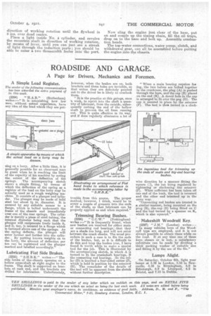
100.—Assembling of Daimler Y Type Engine.
Having bedded the crankshaft, and assembled the connecting rods, with the top half of the crankcase inverted on the engine stand, assemble oil tray and flywheel, and revolve crankshaft. to ensure that bigend dippers do not foul the tray or oil pipes.
Do not put the, timing chain in position. until after the sleeves have been assembled. Place the bottom half of crankcasein position with, say, two or three bolts, and turn the engine over into its normal position. Next lever the eccentric shaft round till No. 1 inner sleeve link is at its highest position. (This can easily be done with a short lever, using one of the studs of the front cover plate as a fulcrum, and prising the teeth of the eccentric shaft driving( wheel.) Then enter piston into sleeve on the bench, using plenty of oil on both surfaces' mount piston on connecting rod, and drive home the gudgeon pin, slide sleeve into position, and the connecting pin will readily enter into sleeve and connecting link. Repeat this operation with Nos. 2, 3, and 4, always bringing the sleeve link to its highest, position. When assembling outer sleeves, use plenty of oil, lever the eccentric shaft round till No. 1 outer sleeve links are in their highest position, which will be found just clears the tap of the cratikease,, and the comaecting pin can readily be entered. Repeat with NoS. 2, 3, 4, then place the cylinders in position and bolt down. •
Now bring the crankshaft into. position with Nos. 1 and 4 on top dead centre, continue to revolve in
• direction of working rotation until the flywheel is 3 ins. over dead centre.
Place a light inside No; 4 cylinder, and revolve the eccentric shaft in direction of working rotation, by means of lever, until you can just see a streak of light through the induction ports ; you should be able to enter a two thousandth feeler into' the port. Now sling the engine just clear of the base, put on and couple up the timing chain' fill the oil trays, drop on to the base and bolt up. Assemble combustion heads.
The top 'water connections, water pump, clutch, and withdrawal gear, can all be assembled before putting thes engine into the chassis.