 1
1 2
2 3
3 4
4 5
5 6
6 7
7 8
8 9
9 10
10 11
11 12
12 13
13 14
14 15
15 16
16 17
17 18
18 19
19 20
20 21
21 22
22 23
23 24
24 25
25 26
26 27
27 28
28 29
29 30
30 31
31 32
32 33
33 34
34 35
35 36
36 37
37 38
38 39
39 40
40 41
41 42
42 43
43 44
44 45
45 46
46 47
47 48
48 49
49 50
50 51
51 52
52 53
53 54
54 55
55 56
56 57
57 58
58 59
59 60
60 61
61 62
62 63
63 64
64 65
65 66
66 67
67 68
68 69
69 70
70 71
71 72
72 73
73 74
74 75
75 76
76 77
77 78
78 79
79 80
80 81
81 82
82 83
83 84
84 85
85 86
86 87
87 88
88 89
89 90
90 91
91 92
92 93
93 94
94 95
95 96
96 97
97 98
98 99
99 100
100 101
101 102
102 103
103 104
104 105
105 106
106 107
107 108
108 109
109 110
110 111
111 112
112 113
113 114
114 115
115 116
116 117
117 118
118 119
119 120
120 121
121 122
122 123
123 124
124 125
125 126
126 127
127 128
128 129
129 130
130 131
131 132
132 133
133 134
134 135
135 136
136 Staying in
Page 130
Page 131
If you've noticed an error in this article please click here to report it so we can fix it.
COn 101
Modern braking systems bristle with electronics and have never been safer. This is how they are controlled!
The Antilock Braking System (ABS) has become an integral part of service braking on modern commercial vehicles. As its name implies, even under the worst road and weather conditions, ABS prevents wheel lock-up when the brakes are applied, ensuring that the vehicle remains steerable and stable. A further benefit is that, in general, braking distances are minimised.
The 'brain' behind the system-the ECU (electronic control unit)-relies on signals it receives from wheel-speed sensors. As the vehicle's wheels rotate, signals are generated in these sensors by the motion of a toothed ring (Sensing ring). The signals enable the ECU to calculate vehicle speed at any time and, importantly, detect any tendency of the wheel to lock up.
The use of advanced electronic software means that, within a quarter of a revolution of the wheel, the ECU is able to detect a potential wheel lock and send an electrical signal to a modulator (electro-pneumatic control valve) sited near the 'problem' wheel.
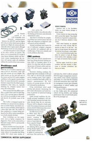
The modulator consists of two electrical solenoid valves. These can be energised independently-one to control the flow of air into the brake actuator, and one to oversee its release to atmosphere. Effective braking pressure can therefore be rapidly modified to stabilise the wheel's braking rate, thereby preventing actual lock and ensuring vehicle stability is maintained.
Importantly, under normal braking conditions-no problems detected by the ECU-the solenoids are not energised and there is no restriction to the passage of air between the foot brake valve and the brake actuators.
Traction control systems (TCS)
The function of a traction control system (also referred to as ASR) is optional and, when specified, forms an integral part of the software programmed into the ECU.
Making use of the information received from the wheel sensors, via additional valves in the service braking system, a slipping wheel or wheels can be automatically braked. So ASR ensures that the drive wheels apply optimum traction to the road when pulling away or accelerating on a slippery surface.
Because all wheels are sensed independently, traction control is possible whether the road is slippery across it's full width or not. An additional feature is also available which will automatically reduce engine speed (and torque at the drive axle) when ASR is activated.
This can be governed by a mechani cal throttle control or via CAN (Controller Area Network) communication between the ABS ECU and the Engine ECU.Also, if a drive wheel starts to slip at speeds over 30kph, the system will automatically reduce engine speed—although the braking circuits are not activated.
An important point to note is that all of the above systems are passive. The driver can be assured that, as a result of close liaison between vehicle and electronic system manufacturers, the systems will operate under all conditions without the need for driver intervention.
Problems and prevention
With the Use Oi modern materials and state-of-the-art electronics, most ABS and ASR systems are very reliable. The wheel sensors are the 'eyes and ears' of the system and the ECU needs complete confidence in the signals it receives from them. To ensure this the ECU constantly monitors output from the wheel sensors, modulators, relay valves, etc., typically checking the complete system once every 100 milliseconds!
Most systems have the ability to produce a simple 'blink-code' for fault diagnosis. If the warning lamp is illuminated, it will then be possible to 'read' a code and identify the probable cause of the fault.
This facility is designed mainly for workshop use and presents its information in number blocks. Each block consists of a series of flashes, which indicate a three-digit fault code. The results are then compared to a master listing produced by the ABS or vehicle manufacturE.r, to finally identify the fault.
Many workshops use test equipment, such as laptop computers, for diagnostics. These can be connected to a dedicated socket which is permanently inked to the ECU.
Vehicle manufacturers have the abilty to fine-tune a standard ABS ECU to Attain optimum performance for a paricular vehicle. So remember that fitting mother ECU which looks similar, or even carries the same base number, may adversely affect the braking performance and ultimately vehicle/driver safety.
Also, bear in mind that the complexity of these new systems means that test bulbs and voltmeters as diagnostic aids will soon be all but redundant.
Instead, workshops must master the use of dedicated computer programs and specialist test equipment such as oscilloscopes, if they are to identify and rectify problems effectively.
EBS arrives
Since 1996 some vehicle manufacturers have been fitting electronic braking systems (EBS) as standard, others as an option. It is clear that, with the continuing increase of features within such systems, EBS will become standard very
SOM.
Electronic braking combines the already high safety standards of ABS and TCS, with an electronically-controlled service braking system. Upon application of a standard foot brake pedal, via modern potentiometers, the ECU receives an accurate picture of the driver's demand for deceleration.
Using conventional wheel speed sensing and pressure monitoring, the ECU sends information to all wheel stations, to generate an optimised braking performance.
Under normal conditions the electrically-activated modulators will provide 'immediate' pressure for brake actuation directly from the air reservoirs. Pressure will be allowed to build until, under the scrutiny of pressure and wheel sensors, the ECU determines that correct deceleration has been achieved.
The EBS reacts as much as 300ms faster than a conventional braking system, resulting in improved stopping distances of more than 6m from a speed of 50mph.
One of the key factors allowing EBS to perform among already highly sophisticated vehicle systems, is its ability to communicate with them. This can be via a
SERVICE POINTERS Excessive heat in the foundation brakes can cause internal damage to wheel sensors.
Friction material can clog sensing ring teeth causing false signals. They should therefore be inspected for physical damage and, if necessary, cleaned at every service.
Check wheel bearings are adjusted correctly and check sensing rings for warping or loose fit to the hub too large an air gap between the sensor and the sensing ring will give a weak signal.
Loose sensors/mounting bushes may allow the sensors to back off. Always renew bushes when replacing a sensor or if signs of excessive heat are apparent.
Electrical cables should be in good condition and held securely in place. Loose or corroded connections can show up as faults.
CAN data bus, which is able to network ECUs for engine management, transmission control, cruise control, suspension and brakes. It is clear that the inclusion of all such innovations into a total vehide management system gives dramatic improvements in vehicle stability and braking performance.
The use of EBS in conjunction with air disc brakes gives the commercial vehicle driving stability and braking performance only ever previously possible in the passenger car.
TYPICAL EBS FEATURES Electronic Stability Program—automatically controls vehicle dynamics by braking appropriate wheels, for example to prevent vehicle roll over.
Adaptive Cruise Control—enables a predetermined distance to be maintained behind the preceding vehicle dependent on speed.
Electronic Levelling Control—enables ride heights to be accurately set and adjusted to suit different operating demands.
Complete load sensing management.
Monitoring and control of brake pad wear to assist with minimising downtime for servicing.
Modulate trailer control line pressures by minimising coupling forces. This gives optimised tractor/trailer compatibility resulting in further improvements in vehicle stability.
Store and monitor general vehicle data such as service interval and preventative maintenance programmes.
Improve tyre wear through more even braking performance.