 1
1 2
2 3
3 4
4 5
5 6
6 7
7 8
8 9
9 10
10 11
11 12
12 13
13 14
14 15
15 16
16 17
17 18
18 19
19 20
20 21
21 22
22 23
23 24
24 25
25 26
26 27
27 28
28 29
29 30
30 31
31 32
32 33
33 34
34 35
35 36
36 37
37 38
38 39
39 40
40 41
41 42
42 43
43 44
44 45
45 46
46 47
47 48
48 49
49 50
50 51
51 52
52 53
53 54
54 55
55 56
56 57
57 58
58 59
59 60
60 61
61 62
62 63
63 64
64 65
65 66
66 67
67 68
68 69
69 70
70 71
71 72
72 73
73 74
74 75
75 76
76 77
77 78
78 79
79 80
80 81
81 82
82 83
83 84
84 85
85 86
86 87
87 88
88 89
89 90
90 91
91 92
92 93
93 94
94 95
95 96
96 97
97 98
98 99
99 100
100 101
101 102
102 103
103 104
104 105
105 106
106 107
107 108
108 109
109 110
110 111
111 112
112 113
113 114
114 115
115 116
116 117
117 118
118 119
119 120
120 121
121 122
122 123
123 124
124 125
125 126
126 127
127 128
128 129
129 130
130 131
131 132
132 133
133 134
134 135
135 136
136 trailer
Page 128
If you've noticed an error in this article please click here to report it so we can fix it.
stoppers
Modern EBS can bring reduced braking, simultaneous anchor and greater control.
The illustration below details typical EBS set-ups for a semitrailer. The system electronically controls lateral braking pressures and consists of the following: a compact, dual-circuit trailer modulator with a digital data interface to ISO 1199-2 to the EBS towing vehicle; a relay emergency valve; load sensor; ABS sensors.
When used on a drawbar trailer or semitrailer with a steering axle, a system is needed which includes an additional EBS relay valve on the steering axles.
Load-sensitive Trailers with the electronic braking sys braking of tern described must be compatible with both semitrailers conventional towing vehicles which use EBS, or ABS thus allowing pneumatic redundant braking in the event of EBS failure.
The trailer EBS mode of functioning can be described in terms of various sub-functions.
Selection of set value: The set value is the driver's braking wish. With operation behind an EBS towing vehicle, the trailer modulator obtains the set value via the trailer interface from the EBS towing vehicle. If no set value is available via the trailer interface (eg when operating the trailer behind a conventionally-braked towing vehicle, or if the trailer interface in the case of EBS trains is interrupted) a set value is generated by measuring the control pressure in the relay emergency valve.
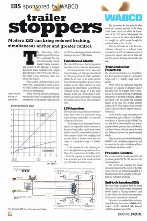
isvantamon The trailer EBS contains the load-dependant brake force control-a distinction being drawn between semi-trailers or centre-axle trailers and full trailers.
The loading state is determined by sensing the air-suspension bellows pressure. In the case of semi-trailers a static linear control device is used. The transmission function of brake pressure (Pzyl) over coupling head, pressure (Pm) is broken down into two ranges-A = Application range, S = Stability range.
In the example the brake cylinder pressure in the application range rises from Pm = 0 bar to Pm= 0.6 bar,from0 to 0.4 barAt Pm = 0.6 bar the response pressure of the wheel brake is reached, and so the vehicle can build up to the brake force as from now.
WABCO
The parameters for this point, in other words the response pressure of the whole trailer brake, can be set within the framework of the EEC bands. Subsequently the brake pressure of the laden vehicle follows the straight line which passes through the calculated value at Pm = 65 bar.
With the full trailer the brake force distribution achieved on a software basis replaces the two LSV controllers common at present, the adaptor valve on the front axle and the pressure limiting valve on the rear axle.
Transmission Function
The transmission function is at present broken down into three ranges: A = Application range, and S = Stability range (refer to graph).
At the end of the application range the pressures are adjusted to optimise wear. A full trailer with, for example, Type 24 cylinders on the front axle and type 20 on the rear, the pressure at the front is reduced a little in accordance with the design and increased slightly at the rear. This ensures uniform loading of all wheel brakes more precisely than is achieved with the adaptor valve currently used.
In the stability range, the pressures of corresponding equal utilisation of adhesion are adjusted as function of the axle load. The rear axle load is determined by the air-suspension bellows pressure. Front axle load is calculated without axle load sensor, from the slip difference between the speed-sensored wheels.
The parameters are calculated using the WABCO brake calculation programme, and are stored in the trailer modulator with the related brake calculation number.
Pressure Control
The pressure control circuits convert the set pressures specified by the LSV function into cylinder pressure.
The control unit compares the actual pressures measured at the output of the relay valves, with the set pressures specified. If a deviation arises this is cancelled out by actuating the ventilation solenoids.
ilaitilockfmaction(ill3S)
The control logic recognises from the speed behaviour of the wheels whether one or more wheels display a 'locking tendency', and decides whether the related brake pressure is to be lowered, maintained or increased.
Each wheel is controlled in its optimum range following this concept-Modified Axle Control (MAR), Modified Side Control (MSR), Individual Control (IR).