


Power assisted Steering Gear
Page 52
If you've noticed an error in this article please click here to report it so we can fix it.
HE application of a 'servo device to • I rack-and-pinion steering mechanism forms the subject of patent No. 735,641. The patent comes from George Kent, Ltd., 199 High Holborn, London, W.C.1.
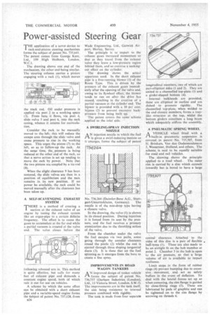
• The drawing shows one end of the mechanism, the other end-being similar. The steering column carries a pinion engaging with a rack (I), which moves the track rod. Oil under pressure is. applied via port 2 to a working space (3). From here. it flows, via port 4, slide valve 5 and port 6, into the rack casing, whence it returns for recirculation.
Consider the rack to be manually moved to the left;• this will reduce the escape area through the slide valve and cause pressure to rise in the working space. This urges the piston (7) to the left, so as to follow-up the rack. At the same time, the pressure is being reduced at the other end of the rack, sothat a servo action is set up tending to move the rack by power. Note that the two pistons are coupled by a tie-rod (a).
When the slight clearance 9 has been restored, the slide valves are then in a position of equilibrium and the rack remains in its new position. If no power be available, the rack could be moved manually after the clearance has been taken up.
A SELF-SCAVENGING EXHAUST SYSTEM
THER is a method of creating a suction at the exhaust valve of an engine by tuning the exhaust system like an organ-pipe to a certain definite frequency. The effect is to cause the gases to accumulate at the far end while a partial vacuum is created at the valve end. The valve closes before the
following rebound sets in. This method is quite effective, but calls for many feet of exhaust pipe and demands a constant engine speed, both of which rule it out for use on vehicles.
A scheme by which the same effect can be obtained with a short exhaust pipe and a variable-speed engine forms the gubject of patent No. 737,128, from B26 Wade Engineering, Ltd., Gatwick Airport, Horley, Surrey.
The principle is to impart to the exhaust gases increased momentum so that as they travel from the cxhausi valve they leave a low-pressure region behind them, an.d.so exercise a sucking.out effect on the cylinder.
The drawing shows . the actual apparatus used. In the short ekhaust pipe is a free-running blower (I) ofthe Roots Type, This k driven. by the pressure of the "exhaust gases immediately after the opening of the valve and, owing to its flywheel effect:the blower tends to run on afterthe drive has ceased,'resulting in the creation of a partial vacuum at the Cylinder end. The blower is provided with a 10 per cent. bypass (2) to prevent, excessive, backpressure from being built up. .
-The patent covers the samescheme 'applied to the inlet side: • A SWIRLING-SPRAYINJECTION NOZZLE AN injection nozzle "in which the fuel is given a swirl-inducing Motion as it emerges, forms the subject of patent
No. 736,264 (Daimler-Benz A.G., Stutt gart-Unterttirkheim, Germany). The nozzle is of the non-drop type having a closure valve. '
In the drawing, the valve (1) is shown in its closed position. During injection it is forced from its seat by the pressure, and the fuel receives a primary atomization due to the throttling action of the valve.
From the chamber under the valve the fuel escapes via two paths, sonic going through the annular clearance round the pintle (2) whilst the rest is ejected through three sloping tangential ducts (3). It is these that set the fuel spinning as it emerges from the bore to create a fine spray.
IMPROVEMENTS IN ROAD WAGON TANKERS
A N improved design a tanker vehicle forms the subject of patent No. 736,757 (Darham Industries (London), Ltd., 13 Victoria Street, London, S.W.1). The improvements are in the tank itself, the aim being resistance to internal pressure combined with rigidity. The tank is made from four separate longitudinal members, two of which are part-elliptical sides (1 and 2). They are united to a channelled top-plate (3) and a girder-shaped bottom (4).
Internal bulkheads are provided; these are elliptical in outline and are dished to promote rigidity. The channelled top-plate, when welded to the end closure members, forms a traylike structure at the top, whilst the bottom girders constitute a long beam which adequately stiffens the assembly.
A PNEUMATIC SPRING WHEEL A VEHICLE wheel fitted with a tl. built-in pneumatic suspension is covered in patent No. 735,507, from H. Brinkers, Van den Oudermeulertaan 2, Wassenaar, Holland, and others. The scheme is said to be equally suitable for road and rail vehicles.
The drawing shows the principle applied to a road wheel. The outer rim is carried by a disc which extends inwardly but is bored to have a large central clearance. Attached to the sides of this disc is a pair of flexible • half-tyres (1). These are also made to be an airtight fit on the hub member at point 2. Chamber 3 in the hub is open to the air pressure, so that a large volume of air is available to impart resilience.
Limit stops in the form of rubber rings (4) prevent bumping due to excessive movement, and act as safety buffers in the event of deflation. To deal with the lateral forces set up as when cornering, the rim flange is guided by close-fitting rings (5). These are lubricated by pads of graphite and can be tightened on to the rim flange by screwing on threads 6.