


Fire Fighting Made Easier
Page 36
If you've noticed an error in this article please click here to report it so we can fix it.
THE driver of a fire-fighting appliance normally has only a Limited oppertunity to gain extensive experience of handling the vehicle, but When he is called ealt in an emergency it is of first importance, in the interests of both safety and expediency, that he should be familiar with the controls and that no time should be wasted by
gear-changing •difficulties.
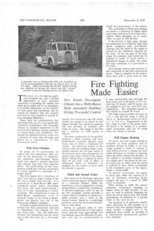
These were the considerations that determined the use of a four-speed fully automatic transmission with two-pedal control as standard equipment in the new F24 fire-appliance chassis produced by Dennis Bros., Ltd., Guildford. The chassis was demonstrated last week over a distance of more than 40 miles and driven by a representative of The Commercial Motor.
Fast Gear Changes
In praise of its performance he reports that the transmission offers not only all the advantages of but eliminates gear-changing delays (both with regard to manual operation and take-up lag) and savesphysical effort. The performance of the transmission would have obvious advantages if it were applied to a passenger or a goods vehicle.
The F24 chassis has a wheelbase of 10 ft. 9 in. and is a larger version of the F8, but is smaller than the F12. It is powered by a Rolls-Royce B80 eight-cylindered petrol engine developing 165 b.h.p., and when tested carried a load of 4 tons, representing a 12-cwt. overload. The transmission is also of Rolls-Royce manufacture a n d is basically similar to that fitted to RollsRoyce and Bentley cars and to the Armstrong Siddeley Sapphire.
A Dennis vehicle fitted with the transmission has been successfully operated by Manchester Fire Brigade for the past three years. The only difference between this installation and the latest type is that the latter has a two-speed
1110
transfer box and power take-off, which. enables the pump to be driven by the engine through the automatic gearbox and also provides an auxiliary low range of ratios. The pump of the F24 has a capacity of 1,000 g.p.m. at 100
The main components of the gearbox comprise a fluid coupling and three hydraulically actuated epicyclie gear trains, one of which is employed for reverse. An important feature of the system is that the coupling forms a connection between the two gear trains of the forward ratios and consequently its speed is less than a third of the engine speed. Idling drag is reduced by more than 50 per cent., and, in effect, is eliminated. There is, therefore, no tendency for the vehicle to move until the throttle is opened.
Third and Second Gears
The clutch of the third-gear epicyclic train is operated against spring pressure by a hydraulic plunger, whilst the second-gear train is engaged by a strong spring which is released by oil pressure. A pressure-regulating valve in one of the two oil-supply systems provides a control which is sensitive to acceleratorpedal position, and a valve in the second system, linked to acentrifugal governor, varies the oil pressure 'according to road speed.
Acting on opposite sides of shift valves, which direct the oil to the appropriate epicyclie train, gear-change timing depends upon the difference in pressure, and can be predetermined to match the performance of the vehicle.
The road speed at which gear changes are made is a function of engine speed and torque, and there is no torque interruption when changing up or down, either on part or full throttle.
If the throttle is fully open, changes areperformed at a 'relatively high road speed, compared with part-throttle running, and the speed of the engine is limited to the minimum required for the load. In the top gear of the high range, for example, road speed can be reduced to about 15 m.p.h. before a downward change is made, but under full load conditions it is performed at 33
Gear-change timing approximates to that employed by the most experienced driver. Figures supplied by the makers show that, with a gross load of over 8 tons, acceleration time through the gears from rest to 20 m.p.h. is 6.75 see. and that 30 m.p.h. and 40 m.p.h. can be reached in 14.5 sec. and 24.75 sec., respectively. The maximum speed of the vehicle is around 60 m.p.h.
The high range provides top gear of 7 to 1 and the low range a ratio of 9.8 to 1. Bottom-gear ratios are 26.75 to 1 or 37.5 to 1. Engagement of the low range (as well as the power takeoff drive) is by means of a synchromesh mechanism and can be made when the vehicle is moving.
Fun Engine Braking
To ensure that full engine braking is available on steep gradients and to facilitate driving in traffic or on very rough ground, a form of control is used which prevents a change up from either third gear or second, as required, when the driver releases the throttle. If the vehicle is travelling relatively fast in a higher gear, movement of the control lever has no effect until the speed is reduced to that which corresponds to the maximum r.p.m. of the engine, which is about 4,000.
To obviate " overreving " the engine in third gear when the control is in use. an automatic overriding device ;engages top gear if a speed of 4,000 r.p.rn. is exceeded.
When driving in traffic the control eliminates unnecessary changing to higher -ratios on light throttle. It can also be used. to prevent changing up when the driver knows that this would immediately be followed by a change down to the ratio in use.
The gearbox is of particular benefit when operating on soft ground, as it obviates lost time during changes and often enables a higher ratio to be employed than would be possible if a conventional synchromesh gearbox were installed.