


A Combined Fluid and Friction Clutch
Page 68
If you've noticed an error in this article please click here to report it so we can fix it.
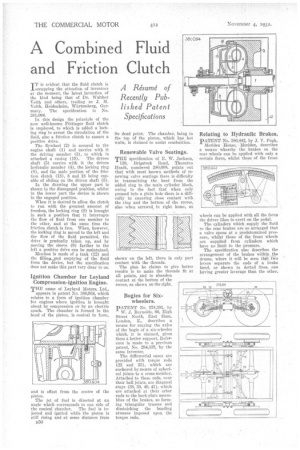
IT is evident that the fluid clutch is occupying the attention of inventors at the moment, the latest invention of the kind being that of Dr. Walther Voith and others, trading as J. M, Voith. Heidenheim, Wiirtemberg, Germany. The specification is No. 381,094.
In this design the principle of the now well-known Fottingcr fluid clutch is 3mployed, to which is added a locking ring to arrest the circulation of the fluid, also a friction clutch to ensure a positive drive.
The flywheel (2) is secured to the engine shaft (1) and carries with it the driving member (3), to which is
attached a casing (19). The driven shaft (5) carries with it the driven hydraulic member (4), the locking ring (8), and the male portion of the friction clutch (18), 8 and 18 being capable of sliding on the driven shaft (5).
In the thawing the upper part is shown in the disengaged position, whilst in the lower part the device is shown in the engaged position.
When it is desired to allow the clutch to run with the greatest amount of freedom, the locking ring (8) is brought in such a position that it interrupts the flow of fluid from one member to the other, and at the same time the friction clutch is free. When, however, the locking ring is moved to the left and the flow of the fluid permitted, the drive is gradually taken up, and by moving the sleeve (9) farther to the left a positive drive can be maintained.
Mention is made of a tank (12) and the filling Ignition Chamber for Leyland Compression-ignition Engine. THE name of Leyland Motors, Ltd., appears in patent No. 380,934, which relates to a form of ignition chamber for engines where ignition is brought about by compression or by an electric spark. The chamber is formed in the head of the piston, is conical in form, and is offset from the centre of the piston. The jet of fuel is directed at an angle which corresponds to one side of the conical chamber. The fuel is injected and ignited while the piston is still rising and at some distance from B50 its dead point. The chamber, being in the top of the piston, which has hot walls, is claimed to assist combustion. Renewable Valve Seatings. THE specification of E. W. Jackson, 139, Brigstock Road, Thornton Heath, numbered 380,608, points out that with most known methods of renewing valve seatings there is difficulty in transmitting the heat from the added ring to the main cylinder block, owing to the fact that when only pressed into a plain hole there is a difficulty in ensuring close contact with the ring and the bottom of the recess, also when screwed. in right home, as shown on the left, there is only part contact with the threads. The plan he claims to give better results is to make the threads fit at all points, and to abandon contact at the bottom of the recess, as shown on the right. Bogies for Sixwheelers. PATENT No. 378,391, by W. J. Reynolds, 66, High Street North, East Ham, London, E., describes a means for staying the axles of the bogie of a six-wheeler which, it is claimed, gives them a better support. Reference is made to a previous patent, No. 294,333, by the same inventor. The differential cases are provided with torque rods (22 and 23), which are anchored by means of spherical joints to a cross-member. Attached to these rods, near their ball joints, are diagonal stays (38, 39, 40, 41), which are attached at their other ends to the back-plate assemblies of the brakes, so forming triangular trusses and diminishing the bending stresses imposed upon the torque rods. Relating to Hydraulic Brakes. PATENT No. 380,442, by J. V. Pugh, Meriden House, Meriden, describes a means whereby the brakes on the rear wheels can be applied with only a certain force, whilst those of the front wheels can be applied with all the force the driver likes to exert on the pedal. The cylinders which supply the fluid to the rear brakes are so arranged that a valve opens at a predetertnined pressure, whilst those of the front wheels are supplied from cylinders which have no limit to the pressure. The specification also describes the arrangement of the brakes within the drums, where it will be seen that two levers separate the ends of a brake baud, as shown in dotted lines, one having greater leverage than the other.Tags