


An Exhaust Braking System
Page 86
If you've noticed an error in this article please click here to report it so we can fix it.
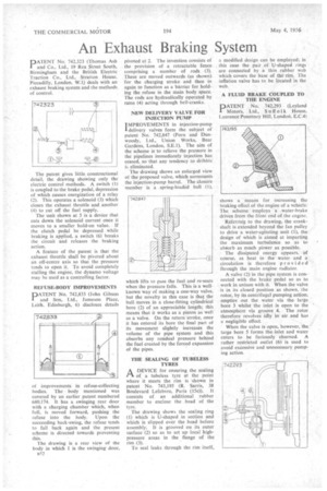
PATENT No. 742,323 (Thomas Ash and Co., Ltd., 19 Rea Street South, Birmingham and the British Electric Traction Co., Ltd., Stratton House. Piccadilly, London, W.1) deals with an exhaust braking system and the methods of control.
The patent gives little constructiona detail, the drawing showing only the electric control methods. A switch (1) is coupled to the brake pedal, depression of which causes energization of a relay (2). This operates a solenoid (3) which closes the exhaust throttle and another (4) to cut off the fuel supply.
The unit shown at 5 is a device that cuts down the solenoid current once it moves to a smaller hold-on value. If the clutch pedal be depressed while braking is applied, a switch (6) breaks the circuit and releases the braking action.
A feature of the patent is that the exhaust throttle shall be pivoted about an off-centre axis so that the pressure tends to open it. To avoid completely stalling the engine, the dynamo voltage may be used as a controlling factor.
REFUSE-BODY IMPROVEMENTS
PATENT No. 742,833 (John Gibson and Son, Ltd., Jameson Place, Leith. Edinburgh, 6) discloses details
ol improvements in refuse-collecting bodies. The body mentioned was covered by an earlier patent numbered 680,174. It has a swinging rear door with a charging chamber which, when full, is moved forward, pushing the refuse into the body. Upon the succeeding back-swing, the refuse tends to fall back again and the present scheme is directed towards preventing this.
The drawing is a rear view of the body in which 1 is the swinging door, n52 pivoted at 2. The invention consists of the provision of a retractable fence comprising a number of rods (3). These are moved outwards (as shown) for the charging stroke and then in again to function as a barrier for holding the refuse in the main body space. The rods are hydraulically operated by rams (4) acting through bell-cranks.
NEW DELIVERY VALVE FOR INJECTION PUMP
IMPROVEMENTS in injection-pump
delivery valves form the subject of patent No. 742,847 (Porn and Dunwoody, Ltd., Union Works, Bear Gardens, London, S.E.1). The aim of the scheme is to relieve the pressure in the pipelines immediately injection has ceased, so that any tendency to dribble is eliminated.
The drawing shows an enlarged view of the proposed valve, which surmounts the injection-pump barrel. The closure member is a .spring-loaded ball (I),
which lifts to pass the fuel and re-seats when the pressure falls. This is a well known way of making a one-way valve but the novelty in this case is that the ball, moves in a close-fitting cylindrica bore (2) of an appreciable length; this means that it works as a piston as well as a valve. On the return-stroke, once it has entered its bore the final part ot its movement slightly increases the volume of the pipe system and this absorbs any residual pressure behind the fuel created by the forced expansion of the pipes.
THE SEALING OF TUBELESS TYRES
I-1 A DEVICE for ensuring the sealing
of a tubeless tyre at the point where it meets the rim is shown in patent No. 743,195 (R. Sarris, 38 Boulevard Lefebvre, Paris (15e)). It consists of an additional rubber member to enclose the bead of the tyre.
The drawing shows the sealing ring (1) which is U-shaped in section and which is slipped over the bead before assembly. It is grooved on its outer surface (2) so as to set up local highpressure areas in the flange of the rim (3).
To seal leaks through the rim itself,
a modified design can be employed; in this case the pair of U-shaped rings are connected by a thin rubber web which covers the base of the rim. The inflation valve has to be located in the web.
A FLUID BRAKE COUPLED TO THE ENGINE
DATENT No. 742,293 (Leyland Motors, Ltd., S u ff o 1k House, Laurence Pountney Hill, London. E.C.4)
shows a means for increasing the braking effect of the engine of a vehicle. The scheme employs a water-brake driven from the feont end of the engine.
Referring to the drawing, the crankshaft is extended beyond the fan pulley to drive a water-agitating unit (I), the design of which is aimed at imparting the maximum turbulence so as to absorb as much power as possible.
The dissipated energy appears, a course, as heat in the water and a circulation is therefore provided through the main engine radiator.
A valve (2) in the pipe system is connected with the brake pedal so as to work in unison with it. When the valve is in its closed position as shown, the rotor, by its centrifugal pumping action. empties out the water via the large bore 3 whilst the inlet is open to the atmosphere via groove 4. The rotor therefore revolves idly in air and has a negligible effect.
When the valve is open, however, the large bore 5 forms the inlet and water enters to be furiously churned. A rather restricted outlet (6) is used to avoid excessive and unnecessary pumping action.