


The Five-ton Pierce-Arrow Chassis.
Page 12
Page 13
If you've noticed an error in this article please click here to report it so we can fix it.
We are able this week to give the following description of the fiveton commercial vehicle recently put out by the Pierce-Arrow Motor Car Co., of Buffalo, New York, which, although not marketed in this country, has a number of sufficientlynovel points to be of interest to our readers ; it is from the designs of Mr. H. Kerr-Thomas, and follows very closely the generally-accepted lines of European construction.
The frame is of pressed steel, and has only three cross-members, properly so called., the central one being of hot-pressed steel, and the two end ones built up from soliddrawn steel tubes which are pressed into steel end castings ; each of these two members is secured to the side members by a single through bolt, this construction allowing great flexibility on uneven roads. The racking strains are provided for by a substantial diagonal brace which is placed behind the rear axle.
The rear springs are perfectly straight when loaded ; they support the frame through double shackles, which are carried from tubular cross-shafts. The front axle is a perfectly-straight drop forging of 1-1 section and allows a road clearance of 121 in. ; the pivot axles, which are also drop forgings, are very short, and, as the wheels are well raked, and have an unusually-wide lock, very-easy steering is assured. The vehicle may be turned inside a circle of 48 ft. in diameter. The steering rods are placed behind the axle, and the steering gear itself is of the nut and screw type. All the wheels run on Timken roller bearings. The rear axle is worm driven, arid is of very-stout construction : the central portion consists of a steel casting with a 104-in. road clearance; the back-axle worm casing is shown in one of the accompanying views. The bearing housings of the worm wheel are cast in one piece with the large circular cover, and the whole assembly of the worm and worm-wheel, with their radial and thrust ball bearings, are removable as one unit, thus permitting easy inspection or repair. The remainder of the axle consists of tapered nickel-steel tubes which are pressed and riveted into the onepiece central casting. Over these tubes are slipped the steel castings which form the spring seats and provide anchorage for the brakes ; these castings are connected, by claw clutches, to the central housing, thus removing all torsional strains from the tubular portion of the axle and transferring the reaction of the brakes direct to the torsion rod, which rod is pivoted in
front of the worm-wheel how_
The worm wheel itself is bolted in the usual way between the two halves of the cast-steel differential case. The tractive and braking strains are transferred from the axle casing to the frame by means of two cast-steel radius rods; these are hinged at their rear ends, and at the front they are attached, by means of universal joints, to caststeel brackets which are bolted to the sides of the frames. These brackets are connected by means of a, steel tube, and they serve also to carry the front end of the torsion rod, and the compensating shaft of the rear-wheel expanding brakes. The general construction of the 40 h.p. engine is shown by the two views reproduced on page 186. The four cylinders are 4i in. in diameter with a 6 in. stroke, the inlet and exhaust valves being placed on opposite sides. Following the regular practice of the Pierce Co., automatic lubrication is provided by means of a rotary pump, which delivers oil into an overhead tank, from whence the oil descends by gravity into the main bearings of the crankshaft ; this shaft is of large diameter, and the hollowed portion serves as a duct through which oil reaches the big ends. There are three bearings to the shaft, and these, as well as the big ends, are of bronze, lined with w hite metal.
A governor, placed within the inlet timing wheel, limits the speed to 900 r.p.m. ; this governor operates on a butterfly valve that is situated immediately above file main throttle valve, which valve is of the rotary form ; the whole of the governor levers and operating rods are enclosed in a case (the illustration shows this case removed), and thus it cannot be tampered with by the driver. Ignition is by Bosch high-tension magneto, and
there is an entirely-separate battery system. Cooling is effected by a centrifugal pump and tubular radiator, the latter having horizontally-disposed gilled tubes which connect up two aluminium tanks.
The suspension of the engine is unique : the rear end of the crankcase is bolted to a. cast-steel crossframe of I section, the supporting bolts passing through the caps of the hind-most bearing of the crankshaft: at the front end a dropforged steel eye is similarly attached to the crankcase, and to this eye is pivoted the girder which supports the front end. The driving spindles of the circulating pump and magneto pass through ample slots in the front-end girder.
The cast-iron flywheel is turned all over, and is secured to the crankshaft by a flanged coupling, to which is also bolted the spigot shaft which acts as a guide for the aluminium clutch; the clutch cone is faced in accordance with the regular practice of the makers— with a bronze liner and a central spring.
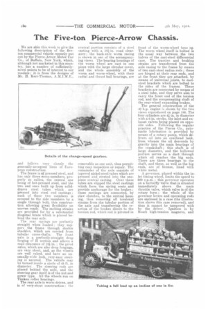
Between the clutch and the gearbox is a universally-jointed shaft about 12 in. long. The three-speed gearbox is shown on page 160; the third speed is direct, and positive interlocking is assured by means of a roller which is placed between V slots in the selector rods. Double ball bearings are provided at both ends of the main shafts, and the cast-steel foot-brake drum, which is provided with a ratchet and pawl to serve as a sprag, is bolted to a flange that forms one -half of the front universal joint of the propeller shaft. It may be mentioned that, by a simple attachment, this sprag cannot be engaged if the reverse is in gear, nor can the latter be used if the sprag is in operation.
The two supporting arms at the rear end of the gearbox are bolted to the pressed-steel cross-frame, whilst the forward end of the box is held by means of a substantial lug through which passes a. tubular shaft that is carried, at its outer ends, by steel brackets which are bolted to the side members of the frame.
The foot brake, which is of the locomotive type, is operated by a spiral cam, on the lines of the Napier design ; the shoes are of cast iron, and are very-easily and cheaply renewable.
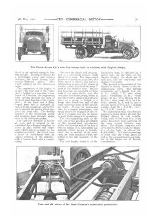
The general arrangement of the chassis is clearly shown in the accompanying views. The leading dimensions are :—length over all, 20 ft. ; width, 7 ft. over wheel hubs ; wheelbase, 13 ft. ; wheel gauge, 69 in. ; tires (front), 36 in. by 5 in. ; tires (rear), 40 in. by 6 in. twin ; speeds, 13, 6, and 3, and a reverse speed of 2i m.p.h. ; chassis weight, 6,400 lb. ; R.A.W., lb. ; F.A.W., 3,000 lb.
We understand that considerable interest is being shown all over the United States in this vehicle, which, with its live rear axle, is an entire departure from anything of the same weight hitherto seen there. The chassis, complete with tires and the driver's cub, but exclusive of the body, is offered for $4,500 (E900). It is also interesting to learn that the worm gears as well as the pressed-steel cross-member of the frame, are of British manufacture.