


Patents Completed.
Page 24
If you've noticed an error in this article please click here to report it so we can fix it.
Complete specifications of the following patents will be sent to any address in the United Kingdom upon receipt of eightpence per copy at Sales Branch, Patent Office, Holborn, W.C.
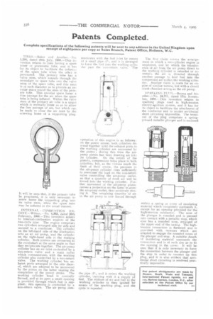
TIRES.—Baker and Another.--No. 1,295, dated 20th July, 1908.—This in. vention relates to tires having a spare inner or pneumatic tube, and it has for its object to facilitate the intiatior of the spare tube when the other is punctured. The primary tube has a valve stem, which extends through the secondary or spare tube into the valve stem ofthe spare tube, and this stem i9 of such diameter as to provide an annular space round the stem of the primary tube. This annular space forms a free passage for the air when the spare tube is being inflated. Within the valve stem of the primary air tube is a spigot which is normally loose so as to allow the free passage of air, but which can be made to close the air inlet by the screwing home of a supporting plug.
It will be seen that, if the primary tube be punctured, it is only necessary to screw home the supporting plug into its valve stem, when the spare tube may be inflated in the usual mariner.
INTERNAL COMBUSTION ENGINE —Wilson.—No. 4,363, dated 26th February, 1908.—This invention relate; to internal-combustion engines of the two-cycle type. The engine comprises two cylinders arranged side by side and secured to a crankcase. The cylinder on the left-hand side of the illustration acts as an air pump, and the cylinder on the right-hand side is the working cylinder. Both pistons are connected to the crankshaft at the same angle so that they reciprocate together. The air-pump cylinder has an air inlet controlled by a non-return valve and a main outlet which communicates with the working cylinder also controlled by a non-return valve. The working cylinder has exhaust ports arranged in the side thereof, which are adapted to be uncovered by the piston on the latter nearing the completion of the power stroke. The working cylinder head is conically formed, and at its apex a small opening is provided through which fuel is supplied; this opening is controlled by a non-return valve. The air pump corn
municates with the fuel illet by means of a small pipe 1.1'1, and it is arranged to force the fuel into the working cylinder past the non-return valve. The
operation of this engine is as follows: on the power stroke, both cylinders descend together until the exhaust ports in the working cylinder are uncovered by the piston ; during this time the airpump piston has been drawing air into its cylinder. On the return of the pistons, compression takes place in both cylinders, but, as the nistons reach the limit of their stroke, the pressure in the air-pump cylinder rises sufficiently to overcome the load on the non-return valve controlling the air-pump outlet, so that a quantity of fresh air will be forced into the working cylinder. Further movement of the air-pump piston causes a projection on the latter to enter the air-pump outlet, thus positively closing it. The remaining quantity of air. in the air pump is now forced through the pipe (P;, and it enters the working cylinder, carrying with it a supply of fuel. The mixture of air and fuel in the working cylinder is then ignited by means of the sparking plug, and the cycle is repeated. The first chum covers the arrangement in which a two-cylinder engine is employed, arid by which the transference of air from the air pump direct to the working cylinder is retarded or arrested ; the air is directed through another passage to feed fuel into the compressed air within the working cylinder. Another claim is made for an engine of similar nature, but with a closed crank chamber acting as the air pump.
SPARKING PLUG.—Brown and Another.—No. 24,711, dated 17th November, 1908,—This invention relates to sparking plugs used in high-tension electric-ignition system, and it has for its object to facilitate the attachment of the conductor 'and to render accidental short circuiting impossible. The terminal of the plug comprises a springpressed metallic plunger and is enclosed within a casing or cover of insulating material which completely surrounds it, except for an opening provided for the high--tension conductor. Thenose of the plunger is rounded and is pressed into contact with a metallic stop, which also has a rounded nose, arranged at the upper end of the casing. The hightension connection is flattened and is provided with recesses which are adapted to engage the rounded noses of the plunger and stop. A suitable sheath of insulating material surrounds the connection and is of such size as to fit the opening in the cover. It will be seen that it is only necessary to force the connection between the plunger and the stop in order to connect up this plug, and it is also evident that accidental short circuiting is rendered practically impossible.