


Patents Completed.
Page 26
If you've noticed an error in this article please click here to report it so we can fix it.
Supporting he Flywheel. A Four-stroke Port Engine.
E. MEDINGER, No. 10,666, dated 6th May, 1913.—In Iwo. cycle engines where the crankcase is used for compressing the air supply for the cylinder, there is a difference of pressure between adjacent crank chambers for different cylinders, and considerable leakage of air may take place through the crankshaft bearing in the dividing wall. If this bearing be made of considerable length to prevent such leakage, the balancing of the engine is rendered more difficult, This specification
describes a method of obtaining a gas-tight joint in the bearing without using an excessive length of bearing. The crankshaft is provided with two conical collars with their retrrow ends towards one another, at each end of the reiddle bearing ; a split bush, which is similarly coned, is mounted on the wall between the two compartments. • When there is a difference in pressure between the two chambers, the unbalanced force causes one of the collars to be pressed closely on its seat so that a long leakage-path is provided, although the total length of the bearing in the dividing wall is but small.
SCIIWEINFURTER PRACISIONS-KUGEL-LAGER-WERKE, UND SACHS, Nu. 22,145, dated under lnternatienal Convention, 22nd August, 1913.—This clutch is sociable for 11SA3 with electric starters, for connecting the starting motor with the engine.
A sprocket wheel, chain driven from the electric motor, is mounted to turn on two side-cheeks, and the latter are in turn mounted on ball bearings on a sleeve connected to the crankshaft of the engine. A series of pawls is mounted between the side cheeks and engages the sprocket wheel in hemispherical recesses. The sleeve is provided with ratchet teeth which are engaged by the other ends of tho pawls to transmit the drive. The general control of this clutch is effected by causing a slight relative rotation between the side cheeks and the sprocket wheel to throw the pawls into or out of engagement as required. This movement may be brought about either by braking, or by suddenly accelerating, one of the elements.
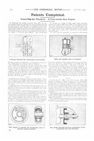
II. FICUER, No. 14,590, of 1913, dated under the International Convention, 28th June, 191a—In this engine a single inlet and exhaust port is used in the cylinder, being uncovered by the piston near the outer end of its stroke. This port communicates with a iacketted chamber at the side of the engine, and cc piston valve reciprocates in the 'chamber across the port.
The inlet front the carburetter is connected to the bottom end of the ch.amber, and the exhuust to the top ; as the piston moves up and down, communication is provided with the inlet and exhaust respectively. The valve is driven in the usual manlier by a two-to-one gear from the crankshaft. At the end of the firing stroke a certain amount of the exhaust gases escape. On the return stroke of the piston some of the exhaust is trapped and compressed, but it is stated that this is sufficiently cooled (from 700 degrees cent. to 80 degrees cent.) during the inward and outward strokes to reduce the pressure so that a new charge can be drawn in. This charge is then compressed and ignited and the cycle again repeated.
E. BUGATTI, No. 1358, dat:•rl 17th January, 1914.—The flywheel is bolted tc a flange on the end of thecrankshaft, outside the crankcase, and a multiple-disc clutch is incorporated with it. A flange is provided on the interior of the flywheel to serve as the clutch casing, and a cover carrying the pies:sure ring is bolted to this flange. This cover is formed integral with a sleeve, for which a bearing is provided on an extension of the crankcase. It will be seen that there is thus a bearing on each side of the flywhe:1 and estillation is thereby minimized.
The propeller shaft has a square head in engagement with a suitably-shaped sleeve carrying one set of the discs for the clutch, and it extends out through the tube which helps to support the flywheel This construction provides for the flywheel and clutch being so supported as to run true, while yet permitting the necessary freedem fer the propetier shaft.