


Hydraulic Variable Gear
Page 52
If you've noticed an error in this article please click here to report it so we can fix it.
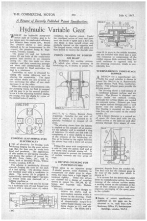
WHILST the hydraulic pump-andVV motor type of variable gear is by no means new, its mechanical efficiency has hitherto been rather low, Patent No. 586,614 shows a new design claimed to be an improvement in this respect, the patentee being R. Segsworth, Toronto, Canada.
The pump (1) and the hydraulic motor (2) are both of the vaned-rotor pattern and revolve in an eccentric casing (3). The two units are close together, and their connecting passages are short and unobstructed, so that losses caused by fluid restriction are kept to a minimum.
Variability of ratio is obtained by sliding the casing sideways and so altering the eccentricity. The input and output shafts are not co-axial, so that increasing the offset of one shaft increases it on the other.
When the casing is set concentric with the pumping vanes, no fluid is pumped and the gear is in the neutral position. Screw 4 is the adjusting member, sliding the casing over the shafts by virtue of the slotted holes (5 and 6).
FORGING LEAF-SPRING EYES ELECTRICALLY
USE of electricity for hearing work during forging has the great advantage that the heat can be made both local and persistent. The application of this system to leaf-spring manufacture forms •the subject of patent No. 585,825, from Omes, Ltd., and G. Mora, both of Beverley Works, Willow Avenue, London, S.W.13.
The scheme is particularly directed towards forging the eyes on the ends of a leaf spring. The drawing shows the machine used with a workpiece in place. The spring (1) is gripped in hydraulically operated copper vice-jaws (2) which form one electrode of a welding machine..
The blade and its vice can be moved by a hydraulic ram (3) and forced into -contact with a shaped anvil (4) which
completes the electric circuit. Under the combined action of heat and pressure, the blade is upset into a boss (5). The blade is then turned about and similarly treated on the opposite end. The forged bosses, which are solid, are then drilled to receive the shackle pins.
PISTON COOLING BY FORCED AIR BLAST
1-1 A SCHEME for cooling pistons, which also allows economy in lubricating oil, is shown in patent No.
586,577, by C. Penco, Buenos Aires, Argentine. Suitable for use with all types of engine, it is claimed to be specially beneficial in respect of oil units.
The drawing shows how the scheme is applied to the cylinder of an engine. To the cylinder wall is attached a ring of injectors (1) which are fed with air compressed to a value slightly in excess of the pressure of the lubricating oil. The air is limited to the region between the piston rings and a lower oil scraper (2), Filling this space with compressed air is said to keep the piston cool and at the same time exclude excess oil. It is also claimed to prevent the formation of carbon between the two series of rings.
A DRIVING COUPLING FOR INJECTION PUMPS 'T'HE drive to an injection pump should possess some flexibility to compensate for slight error in alignment, but must have a high degree of torsional rigidity. These two virtues are claimed for a design of coupling shown in patent No. 586,298, by G. Green and Lagonda Ltd., Staines, Middlesex.
The joint consists of two flanges to receive the shafts, and an intermediate member which is shown in the drawing. Each flange has screwed to it a pair of diametrically opposed rubber-faced blocks, one pair being shown at (1), and the other at (2). The blocks are a close fit in gaps in the middle member, and are bonded with them into a unit. The resistance to compression of the rubber ensures little torsional float, but axial resilience is opposed only by the shearing resistance, which is considerably less.
TURBINE-DRIVEN THREE-STAGE BLOWER
A DESIGN for a supercharger suitrAable for road vehicles is shown in patent No. 586,216 by A. Butterworth, Logger House, Park Way, Camberley, Surrey. The exhaust gases provide the driving power.
The drawing shows a half-section of a combined exhaust turbine and air blower. The blower is disposed centrally inside the exhaust system, although the turbine blades are carried on common rotors. Exhaust gas from the engine arrives through port (1) and passes over the turbine blading (2). The blading is mounted on two rings (one free and one keyed) on the central spindle (3).
On a lesser diameter is a second set of vanes (4); these deal with the air, which arrives at the inlet (5) and after passing through three stages of corn pression, departs from the conduit (6). The final exit for the exhaust gases is by way of the outlet pipe which is shown at 7.
It is claimed for the device that, apart from its supercharging action, the overrunning of the exhaust turbine exerts a sucking action on the cylinders at the end of their exhaust stroke, and thus improves scavenging of the spent gases in the cylinder.