


Control for Petrol-injection Engine
Page 68
If you've noticed an error in this article please click here to report it so we can fix it.
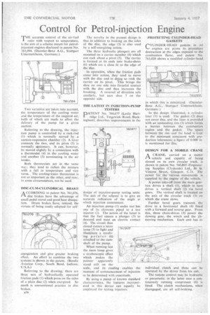
THE accurate control of the air-fuel ratio with respect to temperature, is the aim of a scheme meant for petrolinjectionengines disclosed in patent No. 761,094. (Daimler-Benz A.G., Stuttgart Unterturkheim, Germany.)
Two variables are taken into account, the temperature of the cooling water and the temperature of the inspired air; both of which are made to affect the delivery of the pump for a given suction.
Referring to the drawing, the injection pump is controlled by a rack-rod (1) which is normally moved by a suction-responsive chamber (2). A lever connects the two, and its pivot (3) is normally stationary. It can, however, be moved slightly by a connection with a thermostat (4) in the cooling water and another (5) terminating in the air intake.
Both thermostats act in the same way; they tend to richen the mixture with a fall in temperature and vice versa. The cooling-water thermostat is not so important as the other, and may in some circumstances, not be used.
DISC-CUM-CYLINDRICAL BRAKE
A CCORDING to patent No. 761,076, 2—k disc brakes have the advantage of small pedal travel and good heat dissipation. Drum brakes have, instead, the virtues of being easily adapted for self
energization and give greater braking effect. An effort to combine the two systems is shown in the patent. (Bendix Aviation Corp., South Bend, Indiana, U.S.A.) Referring to the drawing, there are three sets of hydraulically operated friction pads (I) which press on the sides of a plain disc (2) when energized. So much is conventional practice in disc brakes.
B36 The novelty in the present design is that in addition to braking on the sides of the disc, the edge (3) is also used by a self-energizing action.
The three hydraulic plungers are all mounted on a carrier member (4) which can rock about a pivot (5). The carrier is formed at its ends into brake-shoes (6) which are a close fit to the edge of the disc.
In operation, when the friction pads come into action, they tend to move with the disc and in dqing so rock the carrier on its pivot. This brings the shoe on one side into forceful contact with the disc and thus increases the breaking. A reversal of direction acts similarly, but uses shoe 7 on the opposite side.
THE LATEST IN INJECTION-PUMP TESTERS
PATENT No. 760,677 (Leslie Hartridge Ltd., Tingcwick Road, Buckingham), describes improvements in the
design of injection-pump testing units. The aim of the scheme is to give an accurate indication of the angle at which injection commences.
An injection pump (I) under test has one of its elements piped to a test injector (2). The action of the latter is that the fuel causes a plunger (3) to descend and meet an electric contact (4). The circuit thus closed causes a neon lamp (5) to light and illuminate a revolving pointer (6) attached to the camshaft of the pump.
When running fast the neon lamp gives a stroboscopic effect which makes the pointer apparently stand still on the scale, and its reading enables the moment of commencement of injection to be determined with exactitude.
By using a pump of known standard characteristics, the features incorporated in this device can equally be emplo3.ed for testing injectors. PROTECTING CYLINDER-HEAD GASKETS
CYLINDER-HEAD gaskets in oil engines are prone to premature destruction at the edges exposed to the combustion flame, and patent No. 761,020 shows a modified cylinder-head
in which this is minimized. (DaimlerBenz A.G., Stuttgart Unterturkheim. Germany.) In the design illustrated, a cylinder liner (I) is used. The gasket (2) does not cover this, and the liner is provided • with an upstanding rim (3) which forms a barrier between the combustion region and the gasket. The space between the rim • and the head is kept to the minimum consistent with production tolerances; a figure of 0.008 in is mentioned for this.
DESIGN FOR A MOBILE CRANE
ACRANE, carried on a motor vehicle and capable of being stewed on its own circular track, is s-hown in patent No. 760.805 (Engineering Supplies (Clydeside) Ltd., 86 St. Vincent Street, Glasgow. C.2). The power for the various movements is supplied by the engine of the vehicle.
A power take-off from the main gearbox drives a shaft (1), which in turn drives a vertical shaft (2) via bevel gears. The vertical shaft is located on the axis of the circular track (3) on which the crane stews.
Further bevel gears transmit the drive to a horizontal shaft (4) fitted with a forward and reverse gear. From this, three chain-drives (5) power the stewing gear, the winch and the jibmoving mechanism. Each unit has its
individual clutch and these can be operated by the driver from his cab.
The remote control may be hydraulic or pneumatic; in the latter case a continuously running compressor (6) is fitted. The clutch mechanisms, when disengaged, are all self-braking.